ASSA ABLOY ACCENTRA 5400LN Series Cylindrical Locks 5490LN, 5491LN 12VDC or 24VDC Electrified Wiring and Request …_80-9470-0011-000
Open the original PDF document
View PDFElectrified Wiring and Request to Exit (REX) ASSA ABLOY
5490LN/5491LN 12VDC or 24VDC
Installation Instructions
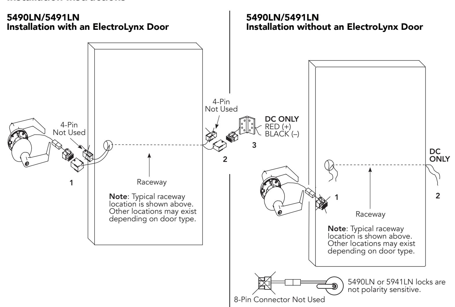
- 1. Plug the lock connector into the mating 8-pin door connector. Install the lock as per the instruction sheets included. (80-9150-0056)
- 2. Verify that the hinge is connected to the door connector.
- 3. Wire the hinge to the power source. Refer to the back side of the page for the wiring of the electric hinge.
- 1. Cut the 8-pin connector from the lockset and strip the remaining wire to 1/4". Strip the wires from the raceway and connect the two ends. Exposed wire must be insulated to prevent fire or shorting of the lockset. By using this method the lockset can be easily disconnected at the remaining connectors if service is required to the lockset.
- 2. Wire the lock to the power source. Refer to the back side of the page for the wiring of the electric hinge.
MARNING
This product can expose you to lead which is known to the state of California to cause cancer and birth defects or other reproductive harm. For more information go to www.P65warnings.ca.gov.
MARNING
Attention Installer: Any retrofit or other field modification to a fire rated opening can potentially impact the fire rating of the opening, and ASSA ABLOY makes no representations or warranties concerning what such impact may be in any specific situation. When retrofitting any portion of an existing fire-rated opening, or specifying and installing a new fire-rated opening, please consult with a code specialist or local code official (Authority Having Jurisdiction) to ensure compliance with all applicable codes and ratings.
1-800-438-1951 • www.assaablov.com
Experience a safer and more open world
ASSA ABLOY
Electrified Wiring and Request to Exit (REX) 5490LN/5491LN 12VDC or 24VDC
Installation Instructions
Installation Notes
- 1. With new applications, a raceway harness with 8- and 4-pin connectors will be pre-installed inside the door by the ASSA ABLOY door manufacturer when specified during the ordering process. Raceway harness kits are available for retrofit applications and for doors manufactured by non-ASSA ABLOY manufacturers.
- 2. Wiring to the pigtail harness is per the facility wiring requirement. Follow the individual instructions below.
- 3. If the door raceway connectors are not present, remove the lock connector and follow the wiring in option A and B.
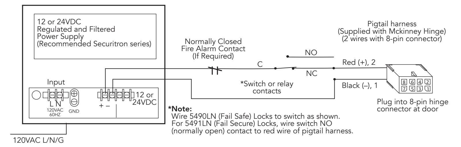
Option A
Sample wiring 5490LN series solenoid locks with a 12 or 12VDC regulated and filtered power supply. (Wiring shows the power on and the lock in the secure state.)
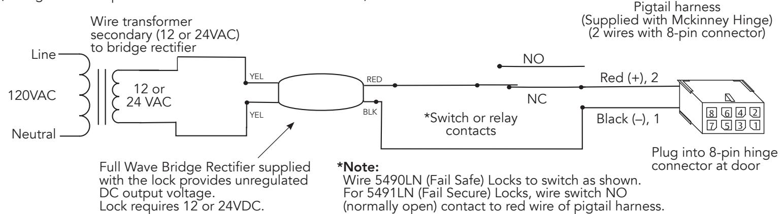
Option B
Sample wiring 5490LN series solenoid locks with a 12 or 12VDC transformer and bridge rectifier supply. (Wiring shows the power on and the lock in the secure state.)
80-9470-0011-000 10/23
Electrified Wiring and Request to Exit (REX) 5490LN/5491LN

Installation Instructions
12VDC or 24VDC
Electric Hinge Wiring
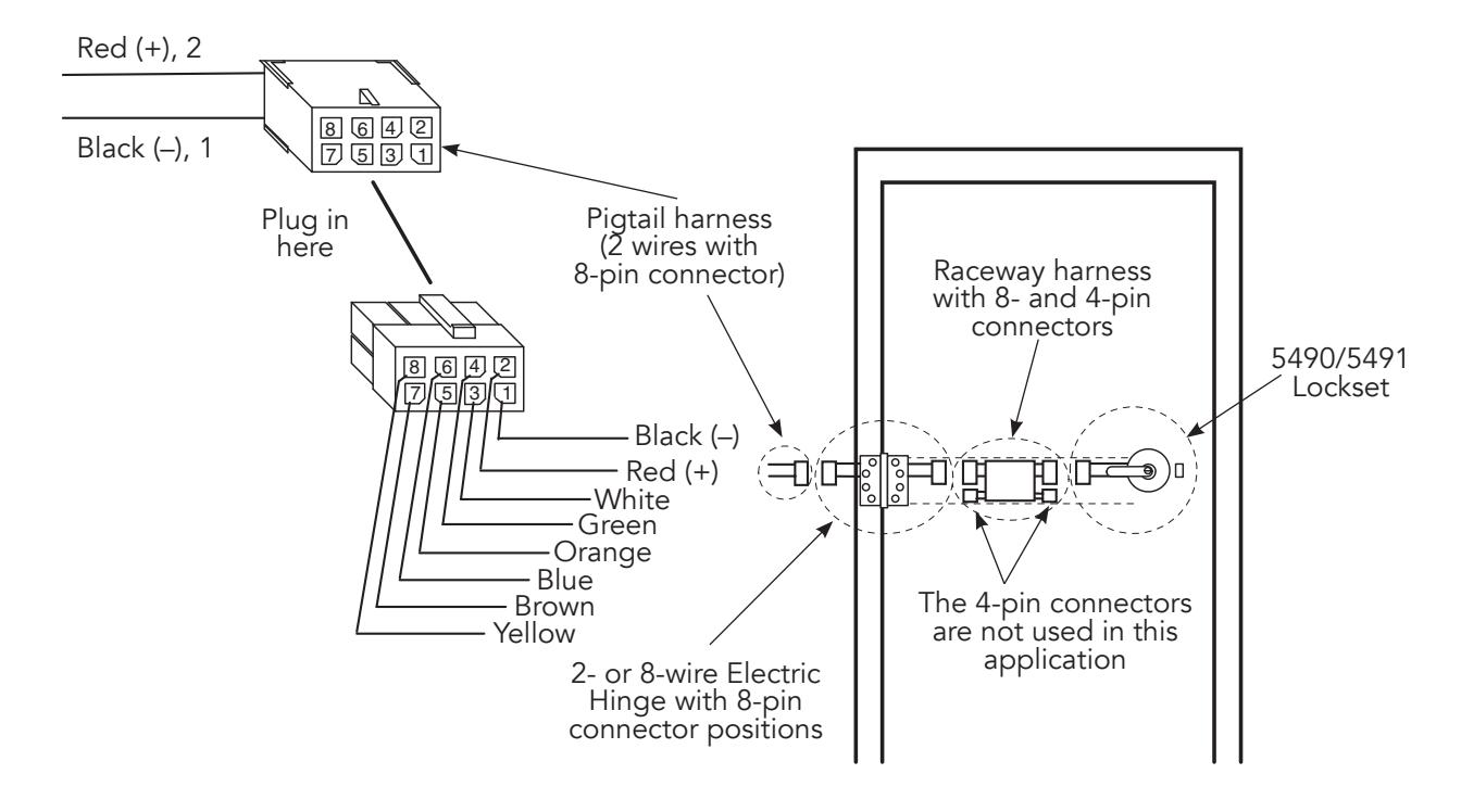
- 1. Wire option A, B (see above), or other wiring requirement to pigtail harness of the hinge.
- 2. Ensure the proper supply voltage is being applied at the pigtail harness.
Caution: The DC voltage must not vary beyond the 12 V +/- 10% or 24 V +/- 10% depending on the lock solenoid installed. If the voltage falls outside these limits, the lock solenoid may be damaged and/or may not function correctly.
- 3. Plug the pigtail harness 8-pin connector into the electric hinge 8-pin connector.
- 4. Test the lock Applying 12 or 24 VDC unlocks fail secure lock and locks fail safe lock.

REX (Request to Exit Wiring Instructions) 5400LN Electrifi ed and 5400LN Mechanical
The REX feature can be used with 5400LN series Electric or Mechanical locksets. This page applies to installation of both. The REX option can be shipped with the lockset or purchased as a retro-fi t kit for existing applications.
If the REX option is used with an Electric lockset (5490LN/5491LN), see steps 1 thru 3. If the REX is used on a Mechanical lockset, skip to step 3. In both cases, refer to the installation instructions provided with the lockset. The below steps are provided as a guide to aid in installing the connectors.
Step 1
Current 5490LN and 5491LN locksets are confi gured from the factory to be used with ElectroLynx. They are also confi gured to be used with out without the REX option. On the lockset, disconnect the inline connectors and dispose of the 8-pin connector and 1 inline connector when the REX option is being used.
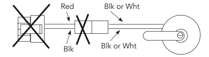
Step 2
Connect the inline connector of the lockset to the inline connector of the REX Inside Assembly through the 1-1/8" hole of the door.

Caution: Do not allow the lockbody to hang off the wires.
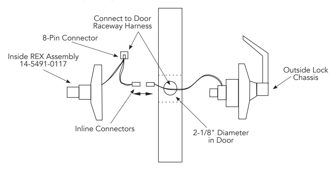
Step 3
Connect the 8-pin connector of the REX assembly to the 8-pin connector from the raceway of the door. Excess wire and the connector should be inserted into the raceway to avoid pinched or cut wires. Insert the outside lock chassis through the 2-1/8" hole. Carefully install the inside REX assembly (refer to the lockset installation instructions). Again, avoid pinching or cutting the wires.
Note: Refer to the below illustration for wire defi nitions
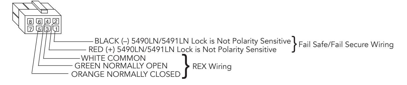
80-9470-0011-000 10/23