ASSA ABLOY ACCENTRA 3000 Series Door Closers Catalog_42072
Open the original PDF document
View PDF

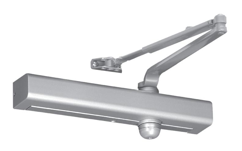
3000 Series Architectural Door Closer
Introduction

| Introduction | 2 |
|---|---|
| Features & Benefits | 3 |
|
Overview
|
4 |
|
Fasteners
|
5 |
|
Features
|
6 |
| Optional Features7 | |
| Finishes | 8 |
| How To Order | 9 |
|
Applications
10-12 |
|
|
Technical Details
13-21 |
|
|
Accessories
22-33 |
|
|
Parts List
34-42 |
|
| Suggested Specifications43 |
Contents 3000 Series Door Closer
Yale 3000 Series Architectural Door Closers offer the perfect combination of reliability, aesthetics and durability in today's market. With features such as staked valves, self-drilling/self-tapping screws, rack and pinion design and precise valve adjustment, and a complete range of arm and cover options, the Yale 3000 Series can meet virtually any application challenge.
Offering sophisticated door control for any upscale commercial application, Yale Works for YouSM.
Features & Benefits

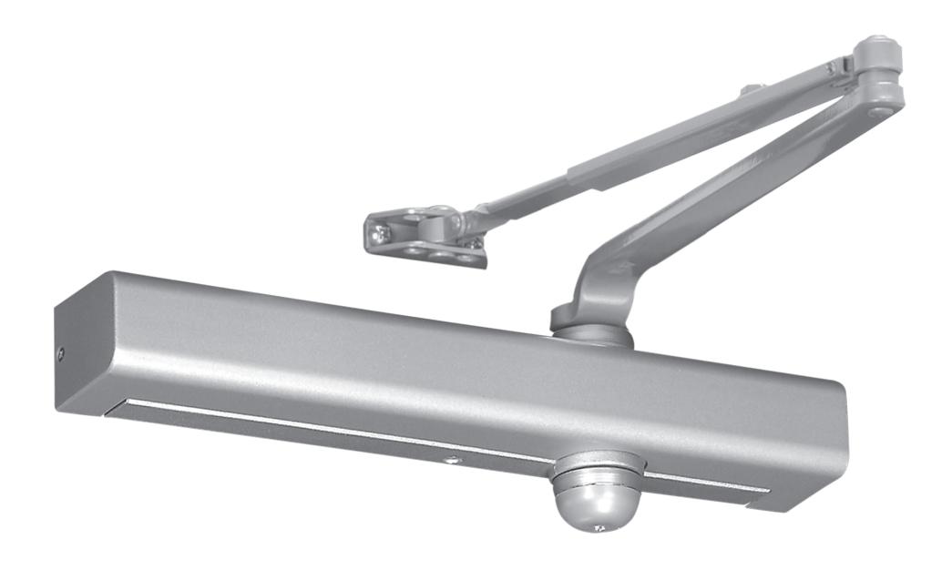
Features
- Exceeds 25 million cycles
- Cast aluminum body
- Adjustable spring sizes 1 through 6
- Tri-packed (regular arm, top jamb and parallel arm mounting)
- Non-handed
- Staked valves
- Rack & pinion design
- 1-1/4" (32mm) diameter piston
- 5/8" (16mm) diameter pinion journals
- Separate and independent, latch, sweep and backcheck intensity valves
- 2-1/8" (54mm) projection (standard covers)
- All standard arm applications (with slim, full or metal covers) allow doors to swing 180 degrees, conditions permitting
Benefits
- Slim profile : Seamless design blends into any building's aesthetic
- Strong & durable : ANSI/BHMA Grade 1 certified for long life and reliability
Optional Features
- Metal and architectural covers (3500 or 3501 only)
- Heavy-duty arms: Parallel Rigid, Holder/Stop, Holder/ Stop Spring, UNI Stop™
- Delayed action
- Lead-lined metal cover (suffix MLL)



Overview

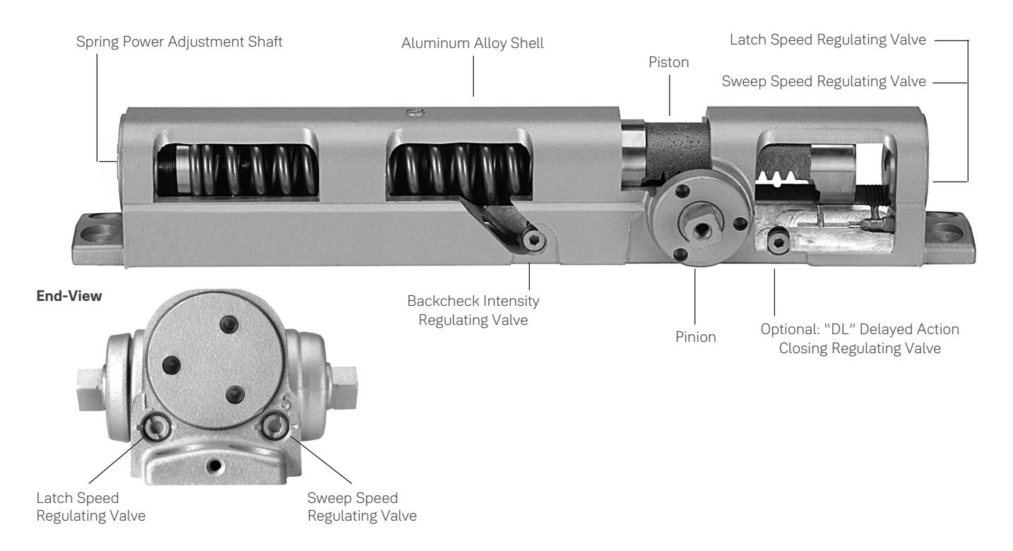
Cutaway View
Compliance Standards
Series 3301 and 3501 door closers are designed to comply with requirements of the Americans with Disabilities Act (A.D.A.) and ANSI standard A117.1. All series 3301/3501 are ANSI/BHMA A156.4 Grade 1 certified. All Yale series 3301/3501 closers with non-hold open arms are listed by Underwriters Laboratories for labeled fire doors. This includes compliance to UL10C for 3-hour assemblies. The product is manufactured in an ISO 9001, ISO 14001 facility.
CAUTION: Door Closers for Low Opening Force Applications:
Door closers installed in openings required to meet the requirements of the Americans With Disabilities Act or ANSI/BHMA Standard A117.1, when adjusted to meet those requirements, may not provide adequate closing power to dependably close and latch the door based on opening or site conditions.
Fasteners

| Arm | |||||||||
|---|---|---|---|---|---|---|---|---|---|
| Type | Description | RA | PA | TJ | Low Profile | PR |
Holder/Stop,
Holder/Stop Spring |
UNI | UNI-J |
| Door | |||||||||
| SDST | Self Drilling Self Tapping | S | S | S | S | S | S | S | S |
| MS | Machine Screw | S | S | S | S | S | S | S | S |
| SN | Sleeve Nut | O | O | O | O | S | S | S | S |
| TBGN | Through-Bolts & Grommet Nuts | O | O | O | O | O | O | O | O |
| SMS | Sheet Metal Screws | O | O | O | O | O | O | O | O |
| Torx® | Torx Drive Security Screw | O | O | O | O | O | O | O | O |
| Frame | |||||||||
| SDST | Self Drilling Self Tapping | S | S | S | S | S | S | S | S |
| MS | Machine Screw | S | S | S | S | S | S | S | S |
| SMS | Sheet Metal Screws | O | O | O | O | O | O | O | O |
| Torx | Torx Drive Security Screw | O | O | O | O | O | O | O | O |
S = standard; O = optional
SN are for use on unreinforced hollow metal doors or to prevent any hollow metal door from collapse/dimpling. They can also be used for thru bolting on wood doors. SN are supplied for 1-3/4" (44mm) thick doors unless specified for 2-1/4" (57mm) thick doors.
TBGN are an alternative to SN for wood doors. TBGN are supplied standard for 1-3/4" (44mm) thick doors. They can be specified for 1-3/8" (35mm) thick doors.
SMS - when specified, closer will be packed with sheet metal screws for the door AND sheet metal screws plus machine screws for the frame.
TORX screws with security pin are standard with Security Door Closers. Torx may be specified for all other series applications. Torx are only available with machine screw threads. Sheet metal screw threads or wood screw threads are not available.
Note: To order special fasteners with closers, specify model number x fastener (Ex: 3501 x 689 x TBGN)
Features

Aluminum Alloy Housing
Closer bodies are constructed of a special aluminum alloy, carefully selected to accommodate interactive steel components and operating conditions.
Rack & Pinion Operation
Provides a smooth constant control of the door through its full opening and closing cycle. 180° door swing can be achieved when door, frame, hardware and arm function do not interfere.
Non-handed
With few exceptions all series and series 3301/3501 door closers are non-handed and can be installed on either right or left hand swing doors. Pinion shaft extends vertically through the closer body in both directions. Some options, as noted on page 5, will require that the hand of the closer be specified.
Sweep Speed Control Valve
Allows adjustment of door speed from the door's full open position down to approximately 10° from the closed position.
Door Closer Power Options Optional Covers
Series 3301/3501 Multi-Sized Door Closer
Adjustable through the power range of sizes 1 through 6, as outlined in ANSI/BHMA specification A156.4.
The series 3000 also conforms to the minimum opening force requirements of the Americans with Disabilities Act (A.D.A) and ANSI/BHMA standard A117.1 for interior doors.
Latch Speed Control Valve
Allows adjustment of door speed from approximately 10° down to the door's fully closed position.
Closer Fluid
All door closers are supplied with a temperature stable, multi-viscosity fluid. This fluid will permit the door closer to perform within a wide temperature range: from very high to as low as -40°F.
Tri-Packed
3301/3501 come with screws, brackets and soffit plates to allow for regular, top jamb, and parallel arm installations.
Adjustable Backcheck Valve
Provides control of the door in the opening cycle, beginning at approximately 75° of door opening. It cushions the door opening when the door is forcibly opened beyond its pre-adjusted limits.
Standard Molded Covers
Molded of high-impact U.L. listed material. Standard covers are non-handed for all applications. See page 5 for optional covers.
Warranty
Limited 30-year warranty for defects and life of the building on the aluminum housing.
Optional Metal Cover
This steel cover is non-handed for regular and parallel arm applications, but is handed for top jamb applications. Cover is available in sprayed or plated finishes.
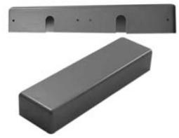
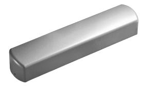
Optional Architectural Covers*
Plastic: Architectural plastic covers are molded of high impact U.L. listed material. They are non-handed and available in sprayed finishes.
Metal: The architectural metal covers are steel and nonhanded for all applications. These covers are available in sprayed or plated finishes.
* For Parallel Arm Applications — Consult factory for doors swinging more than 120°
Optional ABS Cover
Consult factory for details.
Optional Features

Delayed Action
Adjustable Delayed Action Closing
An optional hydraulic feature that adds a third speed range to the closing cycle. This feature becomes effective when the door is opened and released at any point beyond 70°. The amount of time delay depends upon the combination of the angle of door release and valve adjustment. The valve can be adjusted with a 1/8" (3mm) hex key from no delay time up to maximum delay times of:
|
Door Opened and
Released at |
Approximate Time of Delay Cycle |
|---|---|
| 180° | 4-5 minutes |
| 120° | 2-3 minutes |
| 90° | 25-30 seconds |
Pressure Relief Safety Valve
The delayed action hydraulic system contains a pressure relief valve. Any time the door is forced toward the closed direction while it is in the closing cycle, the valve will open and permit the door to close. This prevents damage to door, frame and closer.
Arms
Non-Hold Open
Self-closes door every time door is opened. Auxiliary stop (by others) required except when using the Holder/Stop, Holder/Stop Spring or UNI Stop arms.
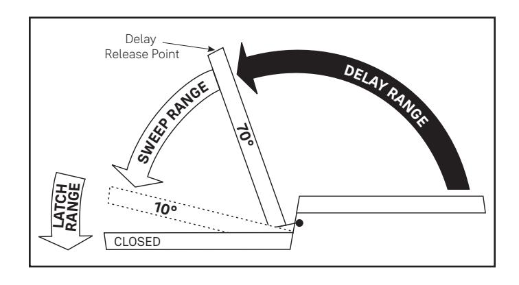
Suggested Applications
Delayed Action closing allows slow-moving traffic to clear the opening before the door closer's normal closing cycle begins. This feature can be helpful in health care facilities such as hospitals and nursing homes. It provides sufficient time for persons on crutches or in wheelchairs to pass through a door without concern of it closing. At the same time, it can accommodate the facility's staff with movement of food service carts, beds, and other wheeled traffic.
Use of delayed action closers on many doors throughout industrial and commercial buildings can also assist the flow of traffic. Locations where additional time to clear the opening is advantageous are doors between office and factory/ warehouse facilities, doors to workshops or laboratories, kitchens and food processing areas.
Hold Open
Achieved by means of friction or ball and detent/roller. Friction hold open has a range of 90° to 180° using template location and mechanical adjustment. Ball and detent or roller hold open is effective in a range of 85° to 110°.
Hold open arm door closers are not permitted to be used on fire door assemblies.
Door Opening Degrees
| Arm Function |
Regular Arm,
Top Jamb, Parallel Arm |
Parallel Rigid
Arm |
Holder/Stop
Parallel Arm |
Holder/Stop
Spring Parallel Arm |
UNI Stop™
Parallel Arm |
UNI Stop™
Top Jamb |
Low
Profile |
|---|---|---|---|---|---|---|---|
| Non-Hold Open | ✓ | / | 85° to 110° | 85° to 110° | 85° to 110° | 85° to 110° | 1 |
| Hold Open | 90° to 180° | 85° to 180° | 85° to 110° | 85° to 110° | 85° to 110° | 85° to 110° | N/A |
✓=180° trim and template permitting
Finishes

Product will be painted with a combination of waterborne acrylic and polyester powder coat. Closers will withstand 100 hours of salt spray. (The ANSI requirement is 25 hours.)
|
ANSI/BHMA Code
Finish Description |
|||
|---|---|---|---|
|
600*
Primed for Painting |
605
Bright Brass, Clear Coated |
606
Satin Brass, Clear Coated |
611
Bright Bronze, Clear Coated |
|
612
Satin Bronze, Clear Coated |
613E
Dark Oxidized Satin Bronze - equivalent |
625
Bright Chrome Plated |
626
Satin Chrome Plated |
|
689
Aluminim Painted |
690
Dark Bronze Painted |
691
Light Bronze Painted |
693
Black Painted |
|
694
Medium Bronze Painted |
696
Satin Brass Painted |
BSP
Black Suede Powder Coat |
WSP
White Suede Powder Coat |
*600 is a special rust-inhibiting prime coat. Closers can be ordered prime coat only (specify closer x 600). An additional charge applies if finish coat is required over prime coat (ex: 3501 x 600 x 689).
| Plated Finishes |
Specify Designation
(ANSI/BHMA) |
Metal Covers Only |
|---|---|---|
| Bright Brass | 605 | Yes |
| Satin Brass | 606 | Yes |
| Bright Bronze | 611 | Yes |
| Satin Bronze | 612 | Yes |
| Bright Chrome | 625 | Yes |
| Satin Chrome | 626 | Yes |
When a plated finish is ordered, arm and metal cover will be plated unless "cover only" is specified. 3101, 3301 - available with plated arm only.
How To Order

For optimum protection of door and frame assemblies, always use auxiliary wall, floor or overhead door stop.
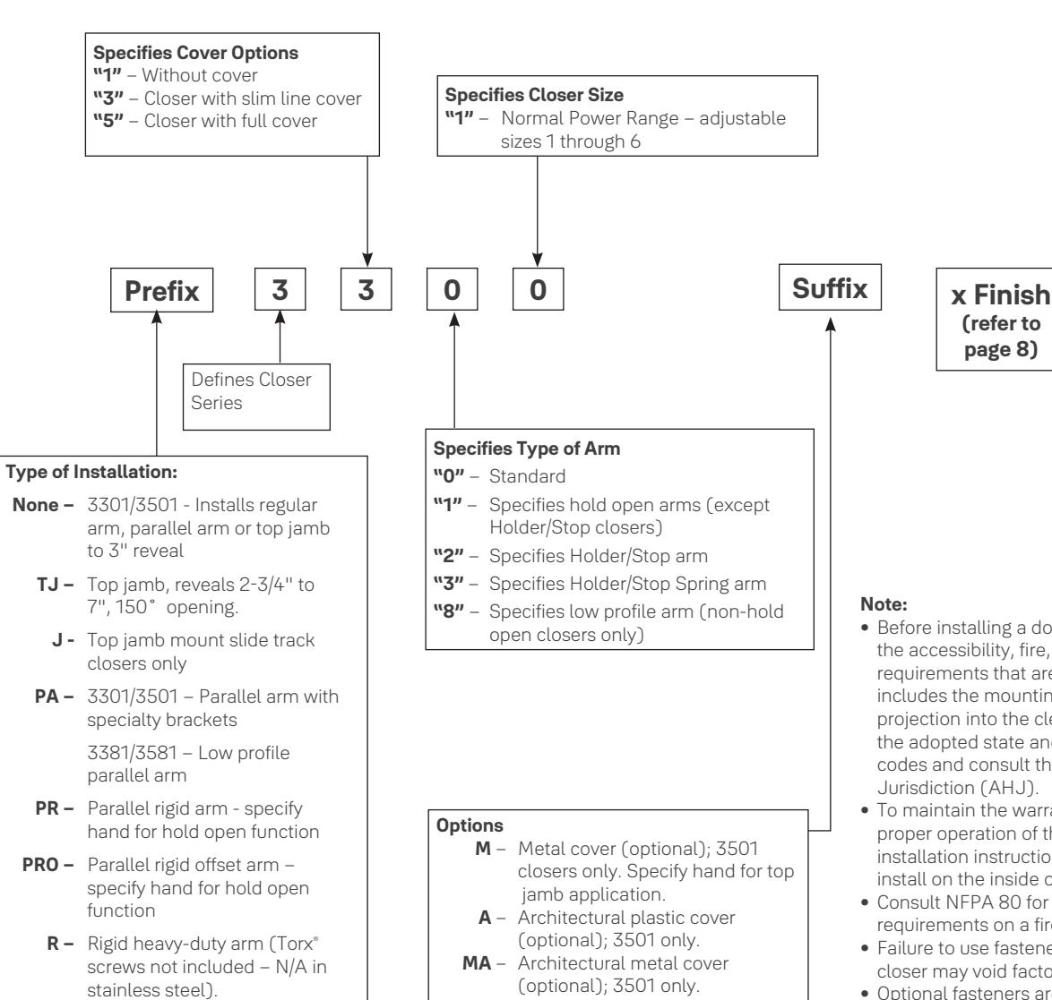
T – Thumbturn hold open on holder/ stop and holder/stop spring arms DL – Adjustable delayed action closing
MLL – Lead-lined metal cover
- Before installing a door closer, verify the accessibility, fire, and life-safety requirements that are in effect. This includes the mounting height and projection into the clear opening. Check the adopted state and local building codes and consult the Authority Having
- To maintain the warranty and ensure proper operation of the product, follow the installation instructions & templates and install on the inside of the building.
- Consult NFPA 80 for the hinge requirements on a fire door.
- Failure to use fasteners supplied with closer may void factory warranty.
- Optional fasteners are available for a variety of applications. Consult the door and frame manufacturer to ensure the proper fasteners are used to maintain certifications.
- Sizing charts are based on 1-3/4" x 7' standard weight doors swinging to 110°. Other application conditions (i.e. larger door heights or weight) may require larger size closer. Adjusting the spring power to meet the low opening force requirements of the Americans With Disabilities Act or ANSI/BHMA Standard A117.1, may not provide adequate closing power to dependably close and latch the door in some conditions (i.e. air movement from wind gusts or building stack pressure).
UNI – UNI Stop™ arm (parallel arm only – specify door width) UNIJ – UNI Stop arm (top jamb only –
specify frame reveal)
Applications

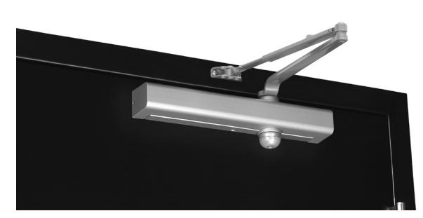
Regular Arm 3501
This is the only pull side application where a double lever arm is used. It is the most power-efficient application for a door closer. Sufficient frame, door and/or ceiling clearance must be considered.
3301
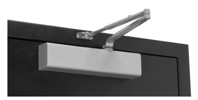
Since the arm assembly projects directly out from the frame, this application may present an aesthetics issue or be prone to vandalism.
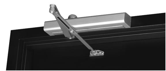
Top Jamb
For efficiency reasons this application provides the best alternative to the regular arm application. There must be sufficient frame face and/or ceiling clearance for this application. It requires a top rail on the door of just 2-1/4" (57mm). This application provides the best door control for doors in exterior walls that swing out of a building.
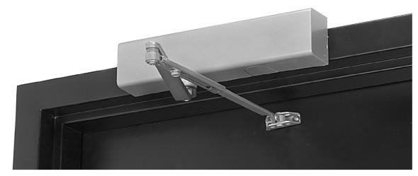
3301 3501
The entire door closer and arm assembly project from the frame, similar to the regular arm application, where matters of appearance and malicious abuse can be of concern. Consideration must be given to depth of reveal.
Parallel Arm
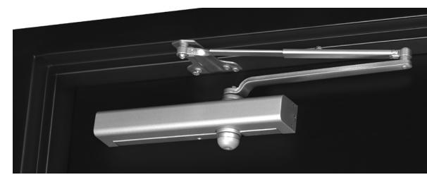
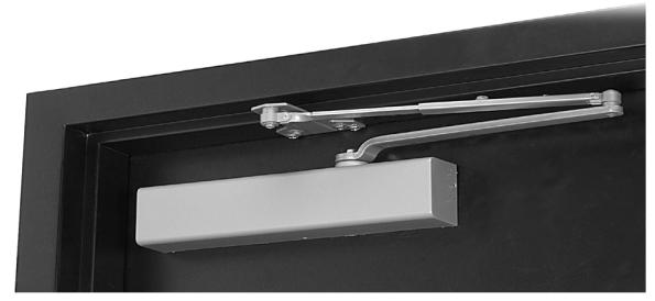
This application provides the most appealing design appearance for a surface-mounted door closer having a double lever arm. This also makes it beneficial in vandalism-prone areas. It is on the push side of the door and the arm assembly extends almost parallel to the door. In the closed position, there is very little or no hardware projecting beyond the frame face in most situations.
3301 3501
Due to the geometry of the arm it is approximately 25% less power-efficient than a regular arm application. The entire closer and arm assembly are mounted below the frame stop. Top rail clearance dimensions will vary based on the type of cover used. (See page 13.)
Applications

Parallel Rigid Arm
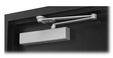
An enhanced variation of the standard parallel arm assembly that is intended for use in heavy traffic areas where auxiliary door stops are installed. Hold open available — specify hand when ordering.
Holder/Stop Arm
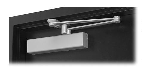
Similar to the Parallel Rigid arm, this arm incorporates a stop at the arm's soffit plate to dead stop the door at a predetermined degree of door swing between 85° and 110°, in 5° increments. Prior to dead stop the door closer's backcheck feature slows the door speed to reduce the impact of the stop action.
The Holder/Stop arm is intended for use where an auxiliary door stop cannot be utilized and no more than moderate abuse is anticipated. Where more extreme conditions are expected, use of a UNI Stop™ arm is recommended. Available with or without hold open. (Hold open strength is adjustable.)
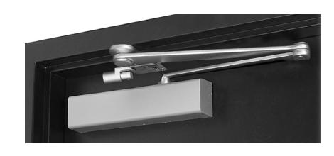
Holder/Stop Spring Arm
This arm has all the characteristics of the Holder/Stop arm with an additional steel buffer spring that providesgreater protection at the end of the door opening cycle. For extreme conditions, use of a UNI Stop arm is recommended. Available with or without hold open.
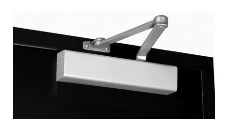
Regular Rigid Heavy-Duty Arm
This double lever arm features a non-adjustable secondary arm. Orbitally riveted joints prevent tampering or disassembly. Prefix "R" to model number. Available non-hold open only.
Applications

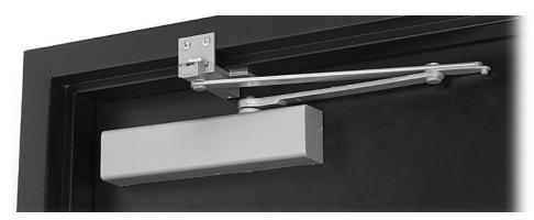
UNI Stop™ Arm
Can be used for either parallel arm or top jamb applications. UNI Stop arms combine the features of a double lever arm overhead door stop/holder with the backcheck feature of the door closer to reduce door stopping shock loads to a minimum. This arm uses a compression spring buffer at the soffit plate/arm shoe that absorbs 30 lbf. of force, 5° prior to the door's dead stop. The UNI Stop arm, coupled with the door closer's
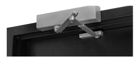
Parallel Top Jamb
backcheck feature, proves the most controlled stop available with a surface door closer.
For parallel arm applications there are three different length arm assemblies. Each length is designed for a specific range of door widths, to provide precise door control. This further lessens the dead stop impact on the door's hinges/pivots.
Only available in painted finishes.
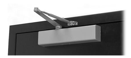
Regular Arm
Allows closer to be installed where there is as little as 1" (25mm) of frame face ceiling clearance
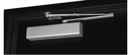
Parallel Arm
Allows closer to be installed 1/2" (13mm) higher up on door than standard parallel arm application.
Low Profile Arm
Supplied with 3381/3581 series door closers for non-hold open installations only. Low profile arms have a reduced height elbow joint and a straight main arm. This enables the door closer to be installed in less vertical space.
Note: Low profile arm door closers are not supplied tri-packed.

Regular Arm
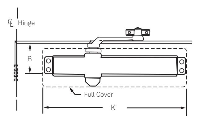
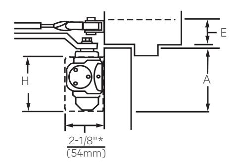
Mounting holes for closer body are spaced 3/4" (19mm) vertically x 12" (305mm) horizontally. Note: All measurements are Inches/mm.
Maximum 180º door swing, conditions permitting
| E | Minimum |
3
n Top Rail |
A
Minimum Top |
|||||||||
|---|---|---|---|---|---|---|---|---|---|---|---|---|
|
Closer
Series |
Covers | Minimu | um Ceiling Clearance | W/O Dr | op Plate |
W/3146
Drop Plate |
Rail Clearance |
K
Closer Length |
H
Closer Height |
|||
| NHO |
Low
Profile |
НО |
NHO/
HO |
Low
Profile |
NHO/
HO |
Low
Profile |
NHO/
HO |
Low
Profile |
||||
| 3100 | No Cover |
12-3/4"
(324) |
||||||||||
| 3300 |
Slim Line
Plastic |
3-1/2"
(89) |
3-3/8"
(86) |
13" |
2-7/8"
(73) |
|||||||
| 3500 | Full Plastic | 1-1/2" | 1" | 1-5/8'' | 2-1/2" |
2-3/8"
(60) |
1-5/8'' |
1-1/2"
(38) |
(330) | |||
| 3500M | Metal | (38) | (25) | (41) | (64) | (41) |
4-1/4"
(108) |
4-1/8"
(105) |
13-5/8"
(346) |
3-3/4"
(95) |
||
| 3500A |
Arch.
Plastic |
3-5/8''
(92) |
3-1/2"
(89) |
14" |
3-1/8"
(79) |
|||||||
| 3500MA |
Arch.
Metal |
3-1/2"
(89) |
3-3/8''
(86) |
(356) |
3''
(76) |
|||||||
| Model Numbers | |||||||||
|---|---|---|---|---|---|---|---|---|---|
| Non-Hold Open | Hold Open | ||||||||
|
3301
3501 |
3311
3511 |
||||||||
Note
Standard door widths 30"-48" (76 - 122cm)
* Projection is for Slim Line or Full Covers. Projection for Metal Covers = 2-3/16" (56mm). Projection for Architectural Plastic & Architectural Metal Covers = 2-1/4" (57mm).

Top Jamb Arm
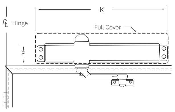
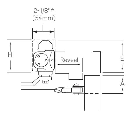
Mounting holes for closer body are spaced 3/4" (19mm) vertically x 12" (305mm) horizontally. Note: All measurements are Inches/mm.
| F | Min |
E
Minimum Ceiling |
A
Minimum Top Rail Clearance |
|||||||||||||||
|---|---|---|---|---|---|---|---|---|---|---|---|---|---|---|---|---|---|---|
| Minim | num Fram | e Face |
Minimum Ceiling
Clearance |
W/O Drop Plate W/3146 Drop Plate | Plate | With 3148/3547 Drop Plate | ||||||||||||
|
Closer
Series |
Covers |
W/O
Drop Plate |
With
3146 Drop Plate |
With
3148, 3158, 3547 & 3547A Drop Plates |
W/O
Drop Plate |
With
3146 Drop Plate |
With
3148, 3158, 3547 & 3547A Drop Plates |
NHO |
Low
Profile |
но | NHO |
Low
Profile |
но | NHO |
Low
Profile |
но |
K
Closer Length |
H
Closer Height |
| 3100 | No Cover |
12-3/4"
(324) |
||||||||||||||||
| 3300 |
Slim Line
Plastic |
1-1/8"
(29) |
1-1/2"
(38) |
2-3/4"
(70) |
1-5/8"
(41) |
1-1/2"
(38) |
13" |
2-7/8"
(73) |
||||||||||
| 3500 | Full Plastic | 1-3/4" | 2-1//." | 2-1/2" | 3-3/8" | 2-3/4" | 3-5/8" | 4-3/8" | 3-3/4" | 4-5/8" | (330) | |||||||
| 3500M | Metal | (44) |
1-5/8"
(41) |
3-3/4"
(95) |
1-5/8"
(41) |
2-1/4"
(57) |
N/A | (64) | (86) | (70) | (92) | (111) | (95) | (117) |
13-5/8"
(346) |
3-3/4"
(95) |
||
| 3500A |
Arch.
Plastic |
N/A | 1-1/2" |
3"
(76) |
N/A | 1-1/2" | 14" |
3-1/8"
(79) |
||||||||||
| 3500MA |
Arch.
Metal |
(38) |
2-7/8"
(73) |
(38) | (356) |
3"
(76) |
||||||||||||
Note: Reveal range information is based upon 1-3/4" (44mm) doors hung on 4-1/2" wide hinges.
* Projection is for Slim Line or Full Covers. Projection for Metal Covers = 2-3/16" (56mm). Projection for Architectural Plastic & Architectural Metal Covers = 2-1/4" (57mm).

Top Jamb Arm
| Model Number | |||||||||
|---|---|---|---|---|---|---|---|---|---|
| Non-Hold Open | Hold Open | ||||||||
|
3301
3501 |
3311
3511 |
||||||||
Note: Standard door widths 30" - 48" (76-122cm)
| Reveal Information | ||||||||||
|---|---|---|---|---|---|---|---|---|---|---|
| Reveal Range | Maximum Door Opening | |||||||||
| Inches (mm) | NHO | Hold Open | ||||||||
| 2-3/4" (70) to 4-1/4" (108) | 180° | — | ||||||||
| 4-1/4" (108) to 7" (178) | 150° | — | ||||||||
| 2-1/8" (54) to 4-1/4" (108) | — | 180° | ||||||||
| 4-1/4" (108) to 6-3/4" (171) | — | 150° | ||||||||
| Reveal Information (regular arm installed top jamb) | ||||||||||
|---|---|---|---|---|---|---|---|---|---|---|
| Reveal Range | Maximum Door Opening | |||||||||
| Inches (mm) | NHO | Hold Open | ||||||||
| 0 to 2-7/8" (73) | 180° | — | ||||||||
| 0 to 2-3/4" (70) | 180° | — | ||||||||
| 0 to 2-3/4" (70) | — | 180° | ||||||||
** Drop Plate 3146, 3148, 3158, 3547 or 3547A
Note: Reveal range information is based upon 1-3/4" (44mm) doors hung on 4-1/2" wide hinges.

Parallel Arm
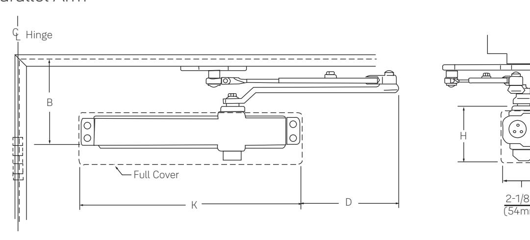
Mounting holes for closer body are spaced 3/4" (19mm) vertically x 12" (305mm) horizontally. Note: All measurements are Inches/mm.
Maximum 180º door swing, conditions permitting.
|
B
Minimum Top Rail 5/8" (16mm) Frame Stop |
А | ||||||||||||
|---|---|---|---|---|---|---|---|---|---|---|---|---|---|
|
Closer
Series |
Covers | W | W/O Drop Plate |
With 3148/3548
Drop Plate |
Top Rail Clearance |
K
Closer Length |
H
Closer Height |
D
Arm Extension |
|||||
| NHO |
Low
Profile |
но | NHO |
Low
Profile |
но | NHO |
Low
Profile |
НО | |||||
| 3100 | No Cover |
12-3/4"
(324) |
8-1/8"
(206) |
||||||||||
| 3300 |
Slim Line
Plastic |
6-1/4"
(159) |
5-5/8"
(143) |
6-1/4"
(159) |
13" |
2-7/8"
(73) |
8" | ||||||
| 3500 |
Full
Plastic |
5-1/4" | 4-5/8" | 5-1/4" | 3" | 2-3/8" | 3" | (330) | (203) | ||||
| 3500M | Metal | (133) | (117) | (133) | (76) | (60) | (76) |
6-7/8"
(175) |
6-1/4"
(159) |
6-7/8"
(175) |
13-5/8"
(346) |
3-3/4"
(95) |
|
| 3500A |
Arch.
Plastic |
6"
(152) |
5-3/8"
(137) |
6"
(152) |
14" |
3-1/8"
(79) |
7-5/8"
(194) |
||||||
| 3500MA |
Arch.
Metal |
5-7/8"
(149) |
5-1/4"
(133) |
5-7/8"
(149) |
(356) |
3"
(76) |
|||||||
| Model Number | ||||||||
|---|---|---|---|---|---|---|---|---|
| Non-Hold Open | Hold Open | |||||||
|
3301
3501 |
3311
3511 |
|||||||
Note
* Projection is for Slim Line or Full Covers. Projection for Metal Covers = 2-3/16" (56mm). Projection for Architectural Plastic & Architectural Metal Covers = 2-1/4" (57mm).

Parallel Rigid Arm
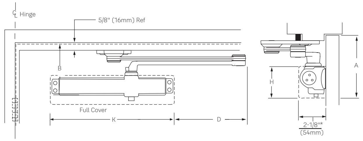
Mounting holes for closer body are spaced 3/4" (19mm) vertically x 12" (305mm) horizontally. Note: All measurements are Inches/mm.
| Classy Savies | Covers |
B
n Top Rail |
A
Minimum Ton Poil |
К | н | D | |
|---|---|---|---|---|---|---|---|
| Closer Series | Covers |
W/O
Drop Plate |
With
Drop Plate |
Minimum Top Rail
Clearance |
Closer Length | Closer Height | Arm Extensions |
| 3100 | No Cover | 5-7/8" |
12-3/4"
(324) |
2-7/8" | 8" | ||
| 3300 | Slim Line Plastic | (149) | 13" | (73) | (203) | ||
| 3500 | Full Plastic | (330) | |||||
| 3500M | Metal |
4-5/8"
(117) |
2-3/8"
(60) |
6-1/2"
(165) |
13-5/8"
(346) |
3-7/8"
(98) |
7-5/8"
(194) |
| 3500A | Arch. Plastic |
6"
(152) |
14" |
3-1/8"
(79) |
7-1/2" | ||
| 3500MA | Arch. Metal |
5-7/8"
(149) |
(356) |
3"
(76) |
(191) |
| Model Number | |||||
|---|---|---|---|---|---|
| Stop Only | Hold Open | ||||
|
PR3301
PR3501 |
PR3311
PR3511 |
||||
* Projection is for Slim Line or Full Covers. Projection for Metal Covers = 2-3/16" (56mm). Projection for Architectural Plastic & Architectural Metal Covers = 2-1/4" (57mm). Standard door widths 28" - 42" (71-122cm)

Holder/Stop Arm
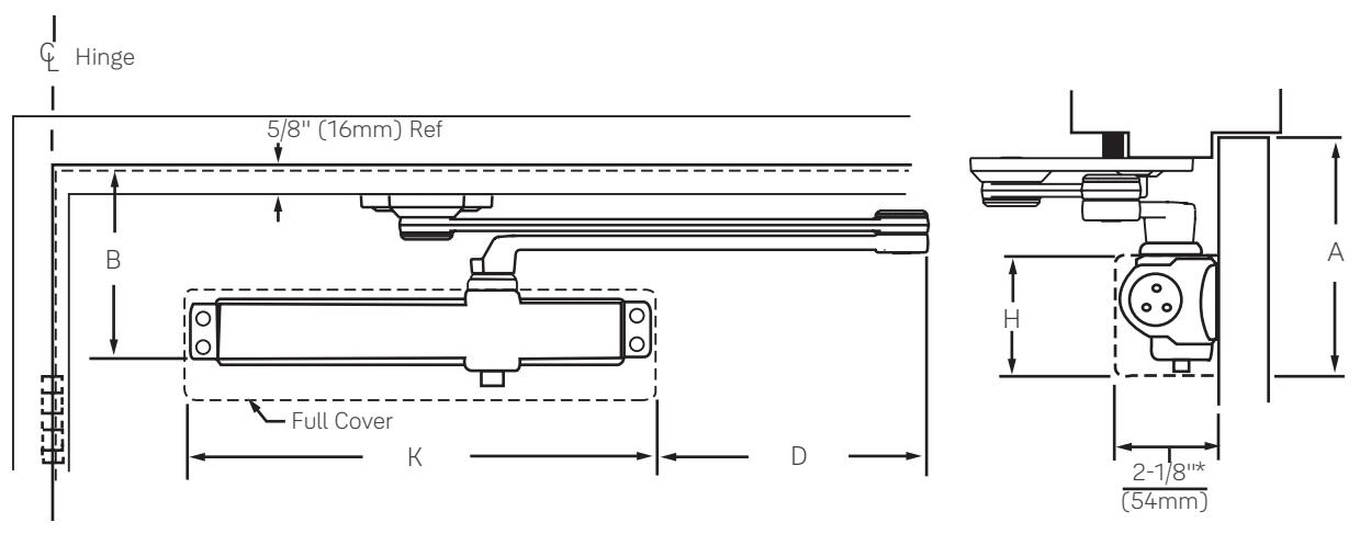
Mounting holes for closer body are spaced 3/4" (19mm) vertically x 12" (305mm) horizontally. Note: All measurements are Inches/mm.
| Closer Series | Covers |
3
n Top Rail |
p Rail Minimum Top Rail |
H
Closer Height |
D
Arm Extensions |
|||
|---|---|---|---|---|---|---|---|---|
| W/O Drop Plate | With Drop Plate | Clearance | Closer Length | Closer Height | Arm extensions | |||
| 3100 | No Cover |
12-3/4"
(324) |
||||||
| 3300 | Slim Line Plastic |
5-7/8"
(149) |
13" |
2-7/8"
(73) |
8"
(203) |
|||
| 3500 | Full Plastic | 4-5/8" | 2-3/8" | (330) | ||||
| 3500M | Metal | (117) | (60) | (60) |
6-1/2"
(165) |
13-5/8"
(346) |
3-7/8"
(98) |
7-5/8"
(194) |
| 3500A | Arch. Plastic |
6"
(152) |
14"
(356) |
3-1/8"
(79) |
7-1/2"
(191) |
|||
| 3500MA | Arch. Metal |
5-7/8"
(149) |
3"
(76) |
|||||
| Model Number | |||||
|---|---|---|---|---|---|
| Stop Only | Hold Open | ||||
|
3321
3521 |
3321T
3521T |
||||
Note
* Projection is for Slim Line or Full Covers. Projection for Metal Covers = 2-3/16" (56mm). Projection for Architectural Plastic & Architectural Metal Covers = 2-1/4" (57mm).

Holder/Stop Spring Arms
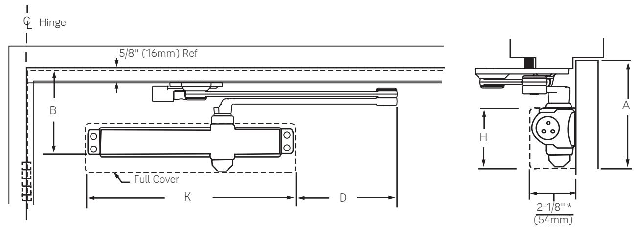
Mounting holes for closer body are spaced 3/4" (19mm) vertically x 12" (305mm) horizontally. Note: All measurements are Inches/mm.
| Closer Series | Covers |
3
n Top Rail |
Minimum Top Rail | н | D | ||
|---|---|---|---|---|---|---|---|
| Closer Series | Covers | W/O Drop Plate | With Drop Plate | Closer Height | Arm Extensions | ||
| 3100 | No Cover |
12-3/4"
(324) |
|||||
| 3300 | Slim Line Plastic |
5-7/8"
(149) 6-1/2" (165) |
13"
(330) |
2-7/8"
(73) |
8"
(203) |
||
| 3500 | Full Plastic | 4-5/8" | 2-3/8" | ||||
| 3500M | Metal | (117) | (60) |
13-5/8"
(346) |
3-7/8"
(98) |
7-5/8"
(194) |
|
| 3500A | Arch. Plastic |
6"
(152) |
14" |
3-1/8"
(79) |
7-1/2" | ||
| 3500MA | Arch. Metal |
5-7/8"
(149) |
(356) |
3"
(76) |
(191) | ||
| Model Number | |||||
|---|---|---|---|---|---|
| Stop Only | Hold Open | ||||
|
3331
3531 |
3331T
3531T |
||||
Note:
* Projection is for Slim Line or Full Covers. Projection for Metal Covers = 2-3/16" (56mm). Projection for Architectural Plastic & Architectural Metal Covers = 2-1/4" (57mm).

UNI Stop™ - Parallel Arm
Mounting holes for closer body are spaced 3/4" (19mm) vertically x 12" (305mm) horizontally.
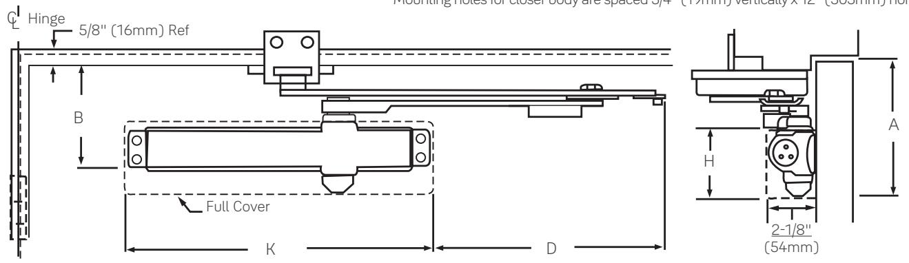
| Oleren Orași | D latt dale | Covers |
B
Minimum Top Rail |
A
Minimum Top Rail |
К | н | D | |
|---|---|---|---|---|---|---|---|---|
| Closer Series | Door Width | Covers |
W/O Drop
Plate |
With Drop
Plate |
Clearance | Closer Length | Closer Height | Arm Extensions |
| 28-32 |
8-3/8"
(213) |
|||||||
| 3300 | 33-41 | Slim Line Plastic | 5-3/4" | 13" | 2-7/8" |
9-7/8"
(251) |
||
| 42-48 | (146) | (330) | (73) |
11-1/4"
(286) |
||||
| 3500 | Full Plastic |
8-3/8"
(213) |
||||||
| 3500M | 20.72 | Metal |
6-3/8"
(162) |
13-5/8"
(346) |
3-7/8"
(98) |
8"
(203) |
||
| 3500A | 28-32 | Arch. Plastic |
5-1/2"
(140) |
14" |
3-1/8"
(79) |
7-7/8"
(200) |
||
| 3500MA | Arch. Metal |
5-3/8"
(137) |
(356) |
3"
(76) |
7-1/2"
(191) |
|||
| 3500 | Full Plastic |
4-3/4"
(121) |
2-1/2"
(64) |
5-3/4"
(146) |
13"
(330) |
2-7/8"
(73) |
9-7/8"
(251) |
|
| 3500M | 33-41 | Metal |
6-3/8"
(162) |
13-5/8"
(346) |
3-7/8"
(98) |
9-1/2"
(241) |
||
| 3500A | 55-41 | Arch. Plastic |
5-1/2"
(140) |
14" |
3-1/8"
(79) |
9-3/8"
(238) |
||
| 3500MA | Arch. Metal |
5-3/8"
(137) |
(356) |
3"
(76) |
9"
(229) |
|||
| 3500 | Full Plastic |
5-3/4"
(146) |
13"
(330) |
2-7/8"
(73) |
11-1/4"
(286) |
|||
| 3500M | /0 /0 | Metal |
6-3/8"
(162) |
13-5/8"
(346) |
3-7/8"
(98) |
10-7/8"
(276) |
||
| 3500A | 42-48 | Arch. Plastic |
5-1/2"
(140) |
14" |
3-1/8"
(79) |
10-3/4"
(273) |
||
| 3500MA | Arch. Metal |
5-3/8"
(137) |
(356) |
3"
(76) |
10-3/8"
(264) |
|||
| Model I | ||||
|---|---|---|---|---|
| Stop Only | Stop Only Hold Open | |||
|
UNI3301
UNI3501 |
UNI3311
UNI3511 |
|||

UNI Stop™ - Top Jamb Arm
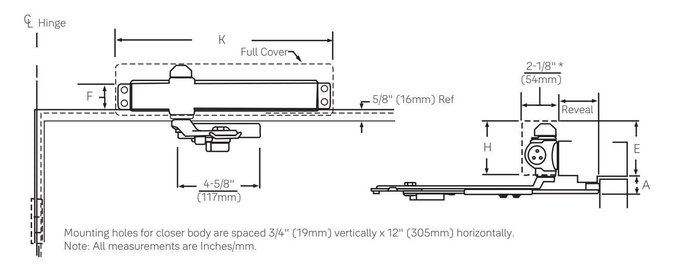
| F E Minimum Ceiling Minimum Frame Face Clearance |
A
Minimum Top Rail Clearance |
К | н | |||||||||
|---|---|---|---|---|---|---|---|---|---|---|---|---|
| Closer Series | Covers |
W/O Drop
Plate |
With 3148,
3158, 3547 & 3547A Drop Plates |
W/O Drop
Plate |
With Drop
Plate |
W/O Drop
Plate |
With 3148,
3158, 3547 & 3547A Drop Plates |
Closer
Length |
Closer Height | |||
| 3300 |
Slim Line
Plastic |
1-1/2" | 2-3/4" | 1-1/2" | 13" | 2-7/8" | ||||||
| 3500 | Full Plastic | (38) | (70) | (38) | (330) | (73) | ||||||
| 3500M | Metal |
1-3/4"
(44) |
1-5/8"
(41) |
3-3/4"
(95) |
1-5/8"
(41) |
1-7/8"
(48) |
3-3/4"
(95) |
13-5/8"
(346) |
3-7/8"
(98) |
|||
| 3500A | Arch. Plastic | 1-1/2" |
3"
(76) |
1-1/2" | 14" | 3-1/8" | ||||||
| 3500MA | Arch. Metal | (38) |
2-7/8"
(73) |
(38) | (356) | (79) | ||||||
| Model I | ||
|---|---|---|
| Stop Only | Hold Open |
x Specify Frame
Reveal |
|
UNIJ3301
UNIJ3501 |
UNIJ3311
UNIJ3511 |
Reveat |
Note:
* Projection is for Slim Line or Full Covers. Projection for Metal Covers = 2-3/16" (56mm). Projection for Architectural Plastic & Architectural Metal Covers = 2-1/4" (57mm).

Regular Arm
Closer Mounting Plates Slim Line Installations
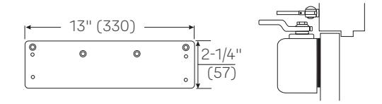
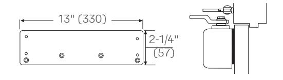
Narrow Top Rail - 3146 Drop Plate: For use where the narrow top rail of the door prevents the closer from being mounted directly on to the door surface. This drop plate must be used for any Series 3000 closer mounted on a top rail between 1-9/16" and 2-7/16" (40 and 62mm) in height, or any 3000 low profile closer mounted on a top rail between 1-7/16" and 2-5/16" (36 and 59mm) in height.
Concealed Door Holder - 3146 Drop Plate: For use where a concealed door holder prevents normal mounting of the closer to the door. This is the same plate used for narrow rail mounting, but is inverted for this application to permit the mounting screws to clear the bottom of the door-holder preparation in the top rail of the door. This places the centerline of the plate's upper mounting screws at 2-3/16" (56mm) from the top of the door.
Full Cover Installations

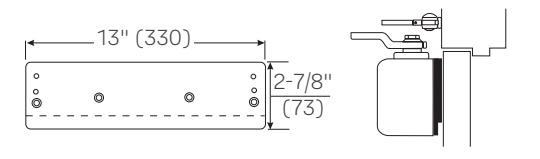
Exposed Back - 3445 Molded Full Cover Decorative Back Plate: For use on doors with glass lights where a closer with a molded full cover is installed and the closer back is exposed. This plate covers the back of the installation to give a pleasing appearance from the reverse side.
Exposed Back/Narrow Top Rail - Exposed Back Concealed Door Holder - 3446 Molded Full Cover Drop Plate Kit: For use with molded full cover installation when a 3146 Plate is needed as a drop plate on a narrow top rail, or as a clearance plate for a concealed door holder, and the closer back is exposed. Kit contains a 3146 Drop Plate and a 3445 Decorative Plate.
Metal Cover Installations
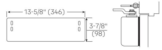
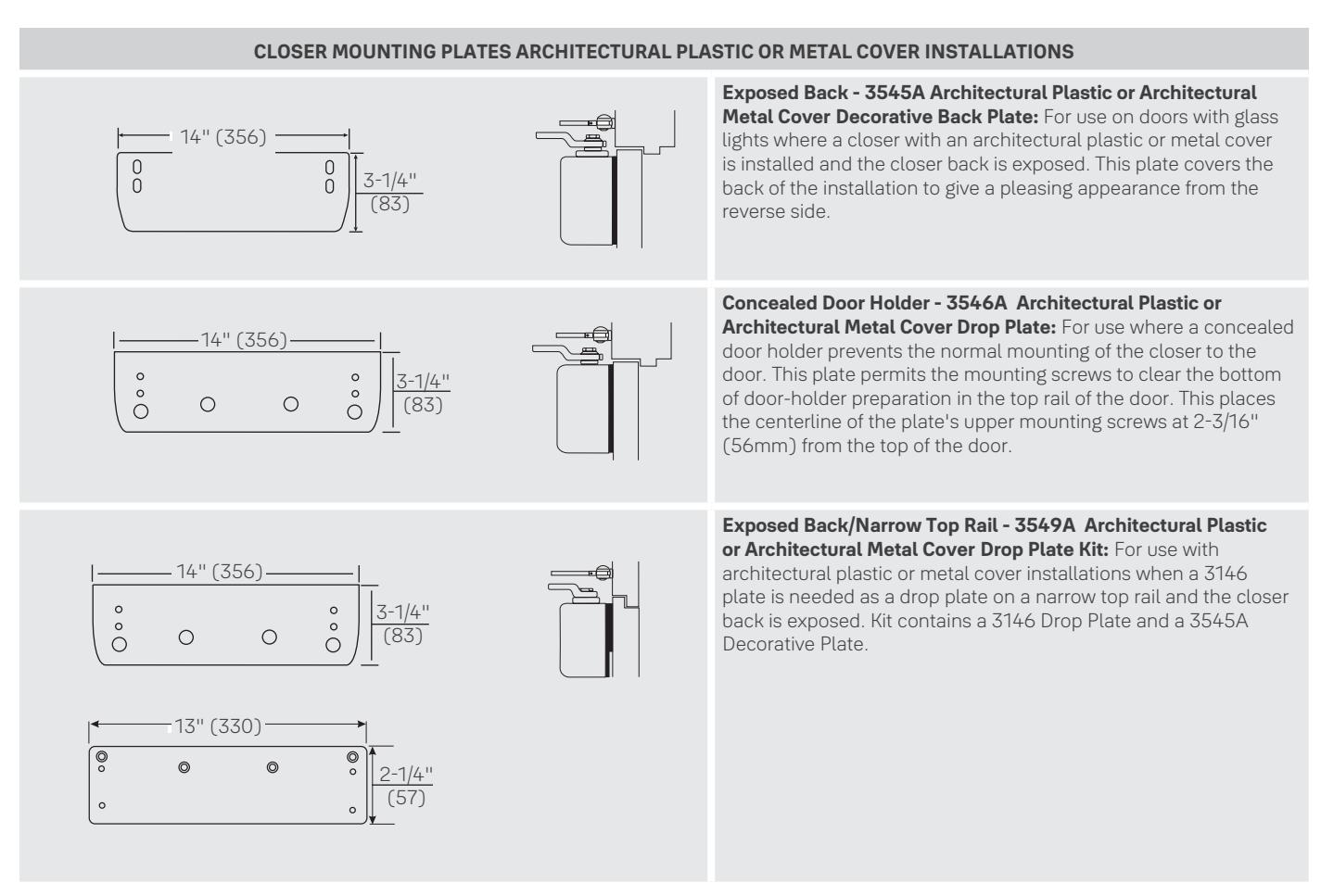
Exposed Back - 3545 Metal Cover Decorative Back Plate: For use on doors with glass lights where a closer with a metal full cover is installed and the closer back is exposed. This plate covers the back of the installation to give a pleasing appearance from the reverse side.
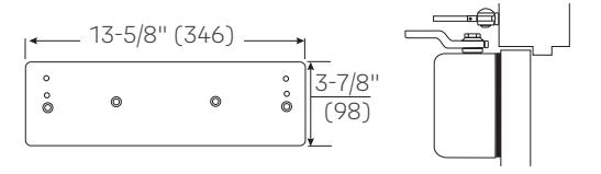
Concealed Door Holder - 3546 Metal Cover Drop Plate: For use where a concealed door holder prevents the normal mounting of the closer to the door. This plate permits the mounting screws to clear the bottom of the door-holder preparation in the top rail of the door. This places the centerline of the plate's upper mounting screws at 2-3/16" (56mm) from the top of the door.
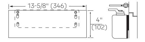
Exposed Back/Narrow Top Rail - 3549 Metal Cover Drop Plate Kit: For use with metal full cover installations, when a 3146 Plate is needed as a drop plate on a narrow top rail and the closer back is exposed. Kit contains a 3146 Drop Plate and a 3545 Decorative Plate.

Regular Arm

Regular Arm
BRACKETS FOR NON-HOLD OPEN ARMS
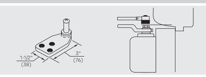
Molded / Bull Nose Trim - 291 Bracket: For use where the door frame has molded or bull nose trim which will not accept a standard non-hold open shoe. The bracket is mortised into the frame rabbet, and projects beyond the face of the frame. It will accommodate a frame rabbet up to 2" (51mm) deep.
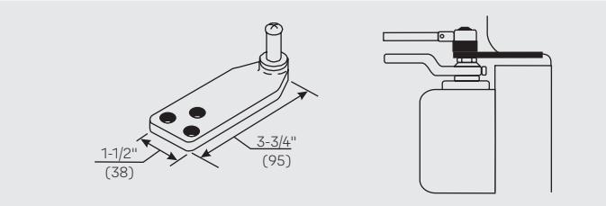
Molded / Bull Nose Trim - 291A Bracket: This bracket is similar to, but longer than, the 291 bracket. It is designed to accommodate frame rabbets from 2" to 2-7/8" (51 to 73mm) deep.
BRACKETS FOR HOLD OPEN ARMS
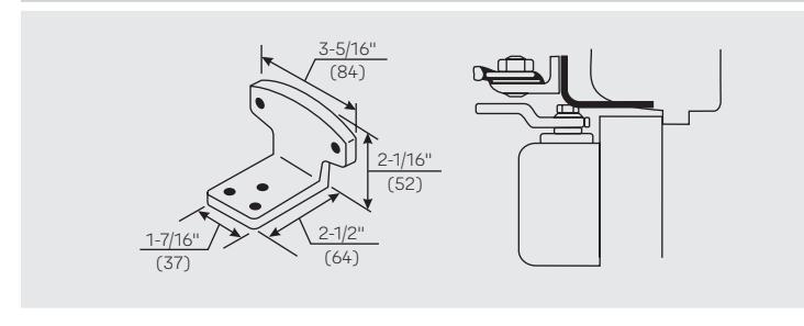
Molded / Bull Nose Trim - 292 Bracket: For use where the door frame has molded or bull nose trim which will not accept a standard hold open shoe. It is mortised into the frame rabbet, and projects beyond the face of the frame. It will accommodate a rabbet up to 2" (51mm) deep. This bracket is used in combination with the standard hold open mounting shoe.
Note: All measurements are Inches/mm.

Top Jamb Arm
CLOSER MOUNTING PLATES SLIM LINE INSTALLATIONS
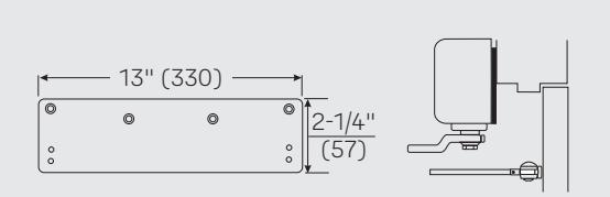
Low Ceiling Clearance - 3146 Drop Plate: For use where low ceiling clearance prevents normal top jamb mounting. This plate is used when clearance is from 1-7/8" to 2-7/8" (48mm to 73mm). Where ceiling clearance is less than 1-7/8" (48mm) see #3148 Drop Plate below.
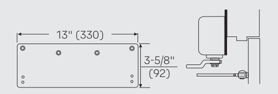
Overhead Door Holder - 3146 Drop Plate: For use where a surface or concealed overhead door holder prevents normal top jamb mounting. This plate drops the closer and allows arm mounting screws to clear the bottom of the door holder. This places the centerline of the arm mounting screws at 2-7/8" (73mm) from the top of the door.
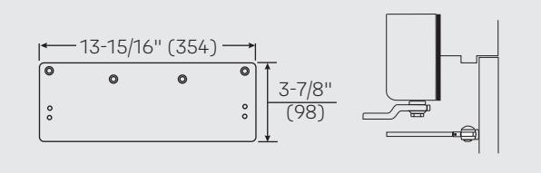
Low Ceiling Clearance - 3148 Drop Plate: For use where the ceiling clearance is between 1-1/2" and 1-3/4" (38 and 44mm).
METAL COVER INSTALLATIONS
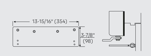
Low Ceiling Clearance - Overhead Door Holder -
3547 Metal Full Cover Drop Plate: For use where a low ceiling clearance prevents normal top jamb mounting. This plate is used when the clearance is between 1-5/8" and 3-7/8" (41mm and 98mm). Or for use where a surface or concealed overhead door holder prevents normal top jamb mounting of a closer with a metal full cover. This plate drops the closer and allows arm mounting screws to clear the bottom of the door holder. This places the centerline of the arm mounting screws at 3-7/8" (98mm) from the top of the door.
ARCHITECTURAL PLASTIC OR METAL COVER INSTALLATIONS
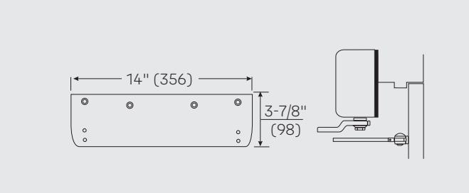
Low Ceiling Clearance - Overhead Door Holder -
3547A Architectural Plastic or Architectural Metal Cover Drop Plate: For use where low ceiling clearance prevents normal top jamb mounting. This plate is used when the clearance is between 1-5/8" and 3-7/8" (41mm and 98mm). Also for use where a surface or concealed overhead door holder prevents normal top jamb mounting of a closer with an architectural plastic or metal full cover. This plate drops the closer and allows arm mounting screws to clear the bottom of the door holder. This places the centerline of the arm mounting screws at 3-7/8" (98mm) from the top of the door.

Parallel Arm

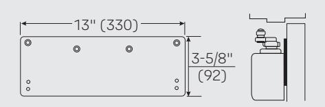
Narrow Top Rail - 3148 Drop Plate (3300 Series): For use where a narrow top rail prevents the closer from being mounted directly to the door surface. This drop plate can be used to mount a closer on a top rail as narrow as 2-7/8" (73mm) in height.
FULL COVER INSTALLATIONS
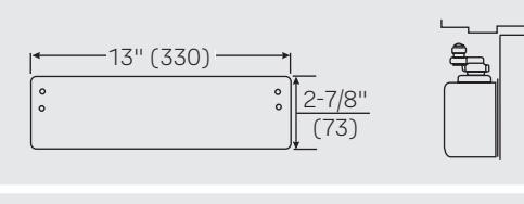
Exposed Back - 3445 Molded Full Cover Decorative Back Plate: For use on doors with glass lights where a closer with molded full cover is installed and the closer back is exposed. This plate covers the back of the installation to give a pleasing appearance from the reverse side.
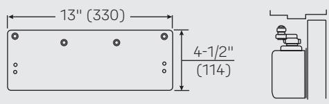
Exposed Back/Narrow Top Rail - 3158 Molded Full Cover Drop Plate: For use on doors with glass lights where a closer with molded full cover is installed and the back of the closer is exposed. This covers the back of the installation and gives a pleasing appearance from the reverse side.
METAL COVER INSTALLATIONS
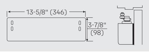
Exposed Back - 3545 Metal Full Cover Decorative Back Plate: For use on doors with glass lights where a closer with full metal cover is installed and the back of the closer is exposed. This plate covers the back of the installation and gives a pleasing appearance from the reverse side.
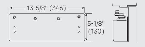
Exposed Back/Narrow Top Rail - 3548 Metal Full Cover Drop Plate: For use on doors with glass lights where a closer with metal full cover is installed on a narrow top rail, and the back of the cover is exposed. This drop plate can be used to mount a closer on a top rail as narrow as 2-7/8" (73mm) in height. This plate covers the back of the installation and gives a pleasing appearance from the reverse side.
ARCHITECTURAL PLASTIC OR METAL COVER INSTALLATIONS
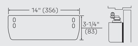
Exposed Back - 3545A Architectural Plastic or Architectural Metal Cover Decorative Back Plate: For use on doors with glass lights where a closer with an architectural plastic or metal cover is installed and the closer back is exposed. This plate covers the back of the installation to give a pleasing appearance from the reverse side.
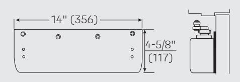
Exposed Back/Narrow Top Rail - 3548A Architectural Plastic or Architectural Metal Cover Drop Plate: For use on doors with glass lights where a closer with an architectural plastic or metal cover is installed on a narrow top rail, and the back of the cover is exposed. This drop plate can be used to mount a closer on a top rail as narrow as 2-7/8" (73mm) in height. This plate covers the back of the installation to give a pleasing appearance from the reverse side.

Parallel Arm - Brackets For Non-Hold Open Arms
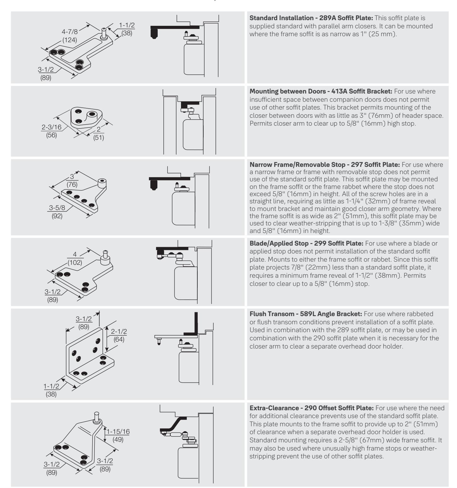

Parallel Arm - Brackets For Non-Hold Open And Hold Open Arms
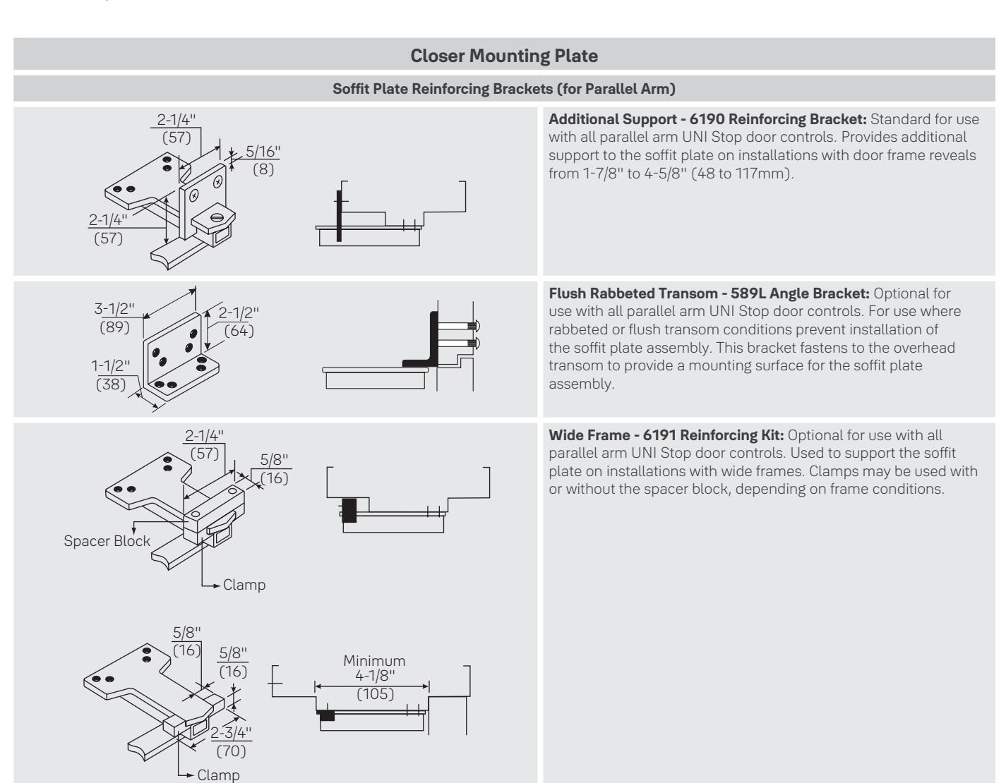
Parallel Hold Open - 588 Adapter Plate: Supplied standard with all parallel arm hold open closers. It can also be used to convert regular arm or top jamb hold open arms to parallel arm installation. It can be mounted where the frame soffit is as narrow as 1" (25mm).
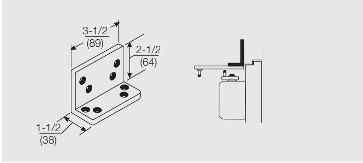
Flush Transom - 589L Angle Bracket: For use where rabbeted or flush transom conditions prevent installation of a soffit plate. Used in combination with the 588 adapter plate, this bracket fastens to the overhead transom to provide a mounting surface for the soffit plate assembly.
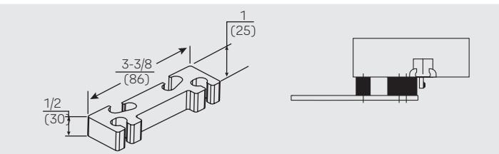
Clearance/Support Blade Stop - 891 Spacer Block: For use where the door frame has a blade stop and the soffit plate must be mounted on the frame rabbet. This accessory is used in combination with the standard spacer block to provide clearance of the blade stop. Also used with non-hold open arms.
Note: All measurements are Inches/mm.

Parallel Rigid, Holder/Stop, Holder/Stop Spring Arms
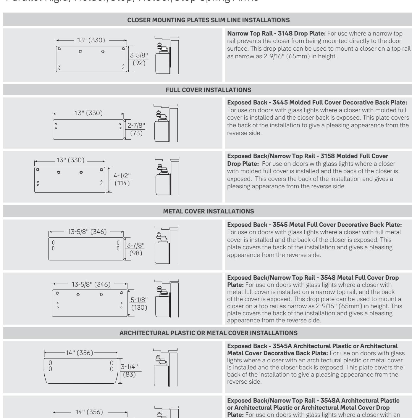
Note: All measurements are Inches/mm.
4-5/8" (117)
pleasing appearance from the reverse side.
architectural plastic or metal cover is installed on a narrow top rail, and the back of the cover is exposed. This drop plate can be used to mount a closer on a top rail as narrow as 2-9/16" (65mm) in height. This plate covers the back of the installation to give a

Parallel Rigid, Holder/Stop, Holder/Stop Spring Arms
BRACKETS FOR NON-HOLD OPEN ARMS & HOLD OPEN ARMS
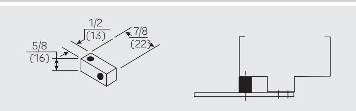
Standard - 293S Spacer Block: For use where a narrow frame soffit does not provide adequate support for the soffit plate. Supplied as standard with all parallel rigid arm closers.
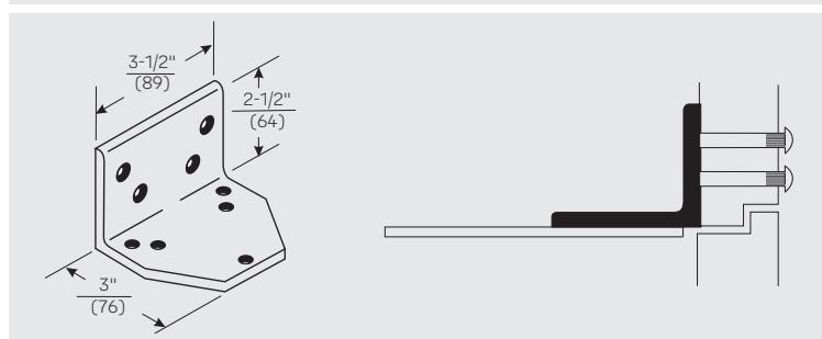
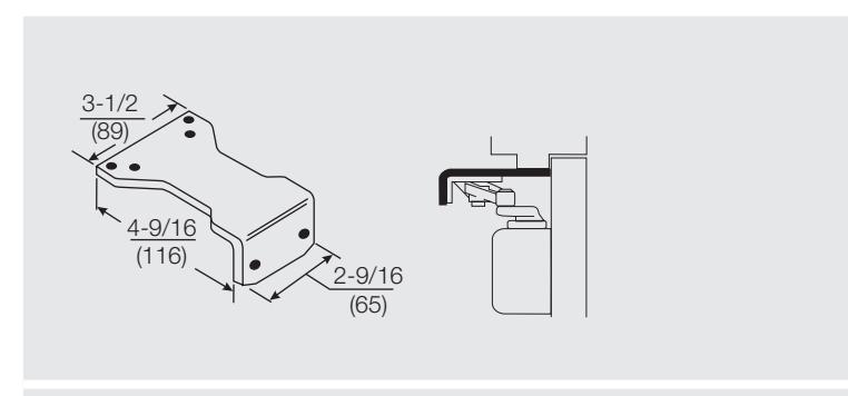
Flush Rabbeted Transom - 293L Angle Bracket: For use where flush transom conditions prevent mounting of the standard soffit plate. This bracket is used in combination with the standard soffit plate.
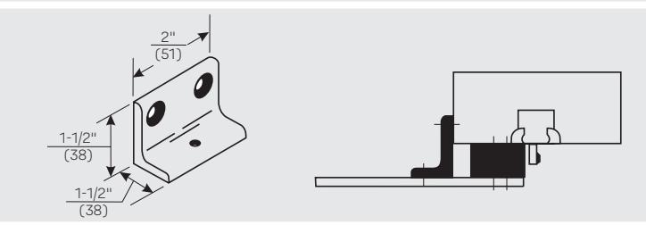
Narrow Frame - 890 Support Bracket: For use where the frame is narrow and the soffit plate cannot be mounted directly to the frame soffit or rabbet. Used in combination with the #891 Spacer Block on blade stop frames to provide extra support and needed clearance of the blade stop. Used on frame where the frame doesn't exceed 5/8" (16mm) in height.
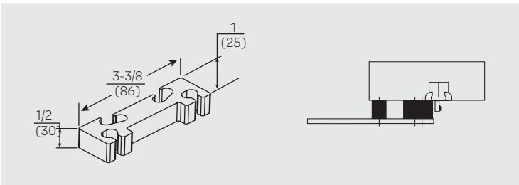
Clearance/Support Blade Stop - 891 Spacer Block: For use where the door frame has a blade stop and the soffit plate must be mounted on the frame rabbet. This accessory is used in combination with the standard spacer block to provide clearance of the blade stop. Also used with non-hold open arms.
Note: All measurements are Inches/mm.

UNI Stop™ Arm
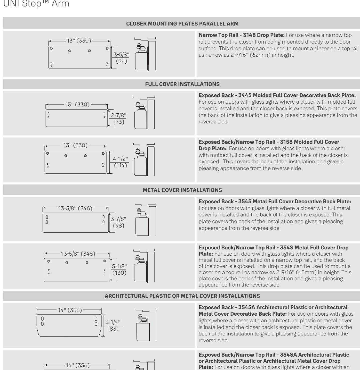
Note: All measurements are Inches/mm.
4-5/8" (117)
pleasing appearance from the reverse side.
architectural plastic or metal cover is installed on a narrow top rail, and the back of the cover is exposed. This drop plate can be used to mount a closer on a top rail as narrow as 2-7/16" (62mm) in height. This plate covers the back of the installation to give a

UNI Stop™ Arm

UNI Stop™ Arm
CLOSER MOUNTING PLATES TOP JAMB
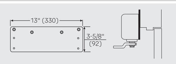
Narrow Top Rail - 3148 Drop Plate: For use where a narrow top rail prevents the closer from being mounted directly to the door surface. This drop plate can be used to mount a closer on a top rail as narrow as 2-7/16"(62mm) in height.
FULL COVER INSTALLATIONS
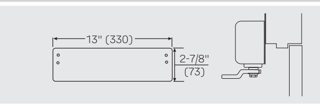
Exposed Back - 3445 Molded Full Cover Decorative Back Plate: For use on doors with glass lights where a closer with molded full cover is installed and the closer back is exposed. This plate covers the back of the installation to give a pleasing appearance from the reverse side.
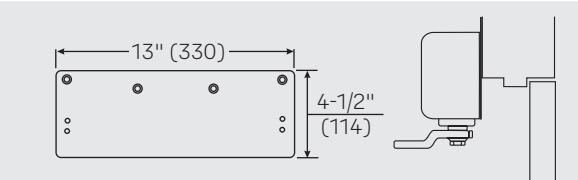
Exposed Back/Narrow Top Rail - 3158 Molded Full Cover Drop Plate: For use on doors with glass lights where a closer with molded full cover is installed and the back of the closer is exposed. This covers the back of the installation and gives a pleasing appearance from the reverse side.
METAL COVER INSTALLATIONS
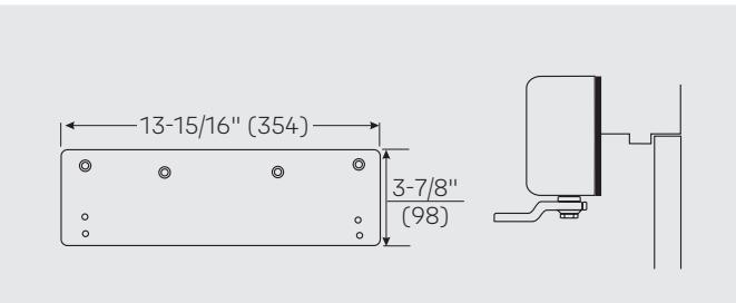
Low Ceiling Clearance - Overhead Door Holder -
3547 Metal Full Cover Drop Plate: For use where a low ceiling clearance prevents normal top jamb mounting. This plate is used when the clearance is between 1-5/8" and 3-3/4" (41mm and 95mm). Or for use where a surface or concealed overhead door holder prevents normal top jamb mounting of a closer with a metal full cover. This plate drops the closer and allows arm mounting screws to clear the bottom of the door holder. This places the centerline of the arm mounting screws at 3-7/8" (98mm) from the top of the door.
ARCHITECTURAL PLASTIC OR METAL COVER INSTALLATIONS
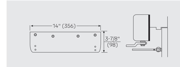
Low Ceiling Clearance - Overhead Door Holder -
3547A Architectural Plastic or Architectural Metal Cover Drop Plate: For use where low ceiling clearance prevents normal top jamb mounting. This plate is used when the clearance is between 1-5/8" and 3-3/4" (41mm and 95mm). Or for use where a surface or concealed overhead door holder prevents normal top jamb mounting of a closer with an architectural plastic or metal full cover. This plate drops the closer and allows arm mounting screws to clear the bottom of the door holder. This places the centerline of the arm mounting screws at 3-7/8" (98mm) from the top of the door.

Door Closer Body Assemblies
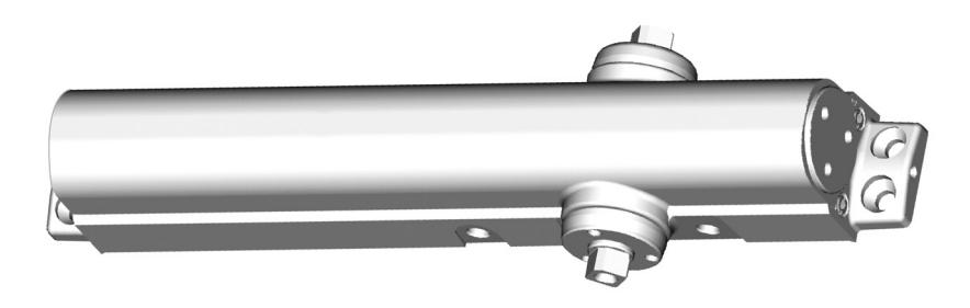
| Model | Description |
|---|---|
| 3101LAP | Multi-sized closer bodies 3101, 3301, 3501 |
LAP = Less All Parts
| Covers | Type of Material | |||||
|---|---|---|---|---|---|---|
| Closer Series | Plastic | Metal | Arch. Plastic | Arch. Metal | ||
| 3301 | 3200P* | N/A | N/A | N/A | ||
| 3501 | 3400P | 3400M | 3400A | 3400MA | ||
Fasteners
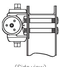
(Side view)
| Steel Door Application Sex-nut / Sleeve-nut : "SN" (4 per pack) or | ||||||
|---|---|---|---|---|---|---|
| Sex-nut / Sleeve-nut & Screw: "SNB" (4 per pack) | ||||||
| Door | SN's | SNB's | ||||
| 4 7// 11 | ON 17/ | OND17/ 70 | ||||
| Door | SN's | SNB's |
|---|---|---|
| 1-3/4" | SN-134 | SNB134-38 |
| 2" | N/A | SNB200-38 |
| 2-1/4" | SN-214 | SNB214-38 |
| S.S. SNB's 1-3/4" | SN-134SS | SNB134SS-38 |
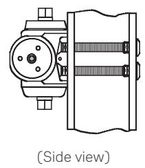
| Aluminum and Wooden Door Application (Aluminum Door Shown) Through-bolt & Grommet Nut : "TBGN" (4 per pack) | ||
|---|---|---|
| Door TBGN's | ||
| 1-3/8" | TBGN138-38 | |
1-3/4" TBGN134-38 2-1/4" TBGN214-38
Note: All measurements are Inches/mm.
Covers
| Cover Model | Cover Drawing |
|---|---|
|
Slim Line*
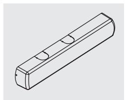
3200P 1-3/4" high x 2-1/8" deep x 13" long (44 x 54 x 330) |
|
|
Full Plastic
3400P |
2-7/8" high x 2-1/8" deep x 13" long
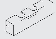
Full Metal 3400M 3-7/8" high x 2-3/16" deep x 13-5/8" long (98 x 56 x 346)
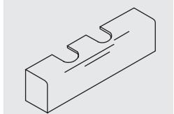
Architectural Plastic 3400A 3-3/32" high x 2-1/4" deep x 13-7/8" long
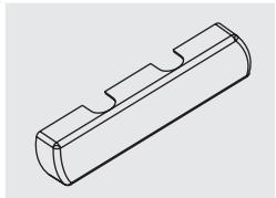
3400MA 3" high x 2-3/16" deep x 13-15/16" long
Architectural Metal
| Arm Type |
Torx
®
Screw Packs |
|---|---|
| Reg., Par. & Top Jamb | TX38 |
| Parallel Rigid, Holder/Stop | PRTX38 |
| Regular Rigid Heavy-Duty Arm | RTX38 |
| UNI Stop™ Arm | UNITX38 |
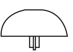
The 1639 pinion cap is NOT included with the 3200P cover. The cap is included with the complete closer package (3300, 3301).

Non-Hold Open Arm Assemblies
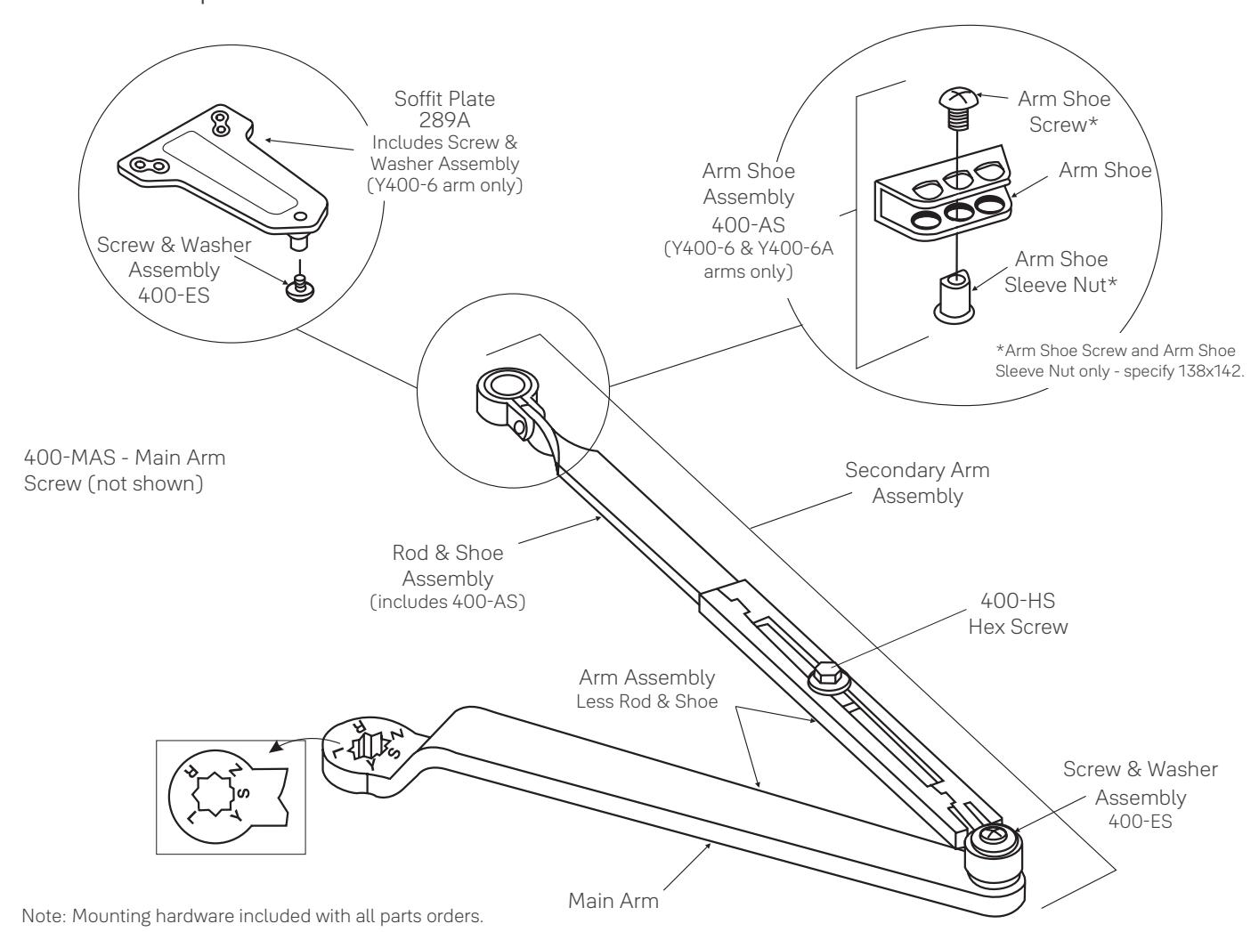
|
Closer
Series |
Complete Arm Assembly |
Main1
Arm Assembly (length)(mm) (includes 400-ES) |
Secondary Arm
Assembly (includes 400-ES) |
Arm Assembly Less
Rod and Shoe |
Rod & Shoe2
Assembly (length)(mm) |
|---|---|---|---|---|---|
| 3000 | Y400-1 | Y400-111 | Y400-11 (8-7/8")(225) | ||
| TJ3000 | Y400-1A | 400-1M | Y400-121 | Y400-1W | Y400-11A (12-9/16")(319) |
| P3000 | Y400-6 | (11")(279) | Y400-116 | Y400-16 (8-7/8")(225) | |
| P30003 | Y400-6A | Y400-116A | Y400-16A (12-9/16")(319) | ||
| 3000 |
Y400-26 (Tri-Packed®
packaging includes Y400-1 plus 289A plate) |
1. C/L to C/L length shown in parentheses.
2. C/L of connecting link to end of rod shown in parentheses.
3. For 180° door swing when using a special template for doors hung on 6" to 8" (162mm to 203mm) wide throw hinges.

Hold Open Arm Assemblies
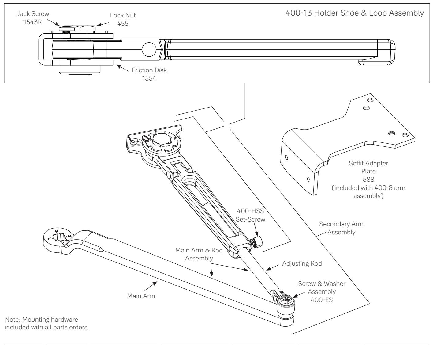
|
Closer
Series |
Complete
Arm Assembly |
Main Arm
1
(Length)(mm) (includes 400-ES) |
Secondary Arm
(includes 400-ES) |
Main Arm & Rod
Assembly |
Holder Shoe & Loop Assembly |
Adjusting Rod
2
(length)(mm) |
|---|---|---|---|---|---|---|
| 3010 |
400-3/
400-8 3 |
400-1M |
400-113/400-118
(Reg.) / (Par.) |
400-3W |
400-13/400-18
4
(Reg.)/(Par.) |
400-31
(7-3/8")(187) |
| TJ3010 | 400-3A | (11")(279) | 400-123 | 400-3WA | 400-13 |
400-31A
(10-13/16")(275) |
400-18- Holder Shoe & Loop Assembly (400-13) with Soffit Adapter Plate (588)
- 1. C/L to C/L length shown in parentheses.
- 2. C/L of connecting link to end of rod shown in parentheses.
- 3. Same as 400-3 but includes #588H soffit adapter plate.
- 4. Same as 400-13 but includes #588H soffit adapter plate

Parallel Rigid Arm Assemblies
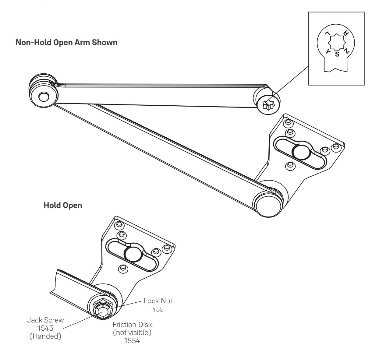
| Arm Function |
Complete Arm
Assembly |
|---|---|
| Non-Hold Open | PR400-5 |
| PR400-8R (Right Hand) | |
| Hold Open | PR400-8L (Left Hand) |

Holder/Stop Arm Assemblies
Hold Open Arm Shown
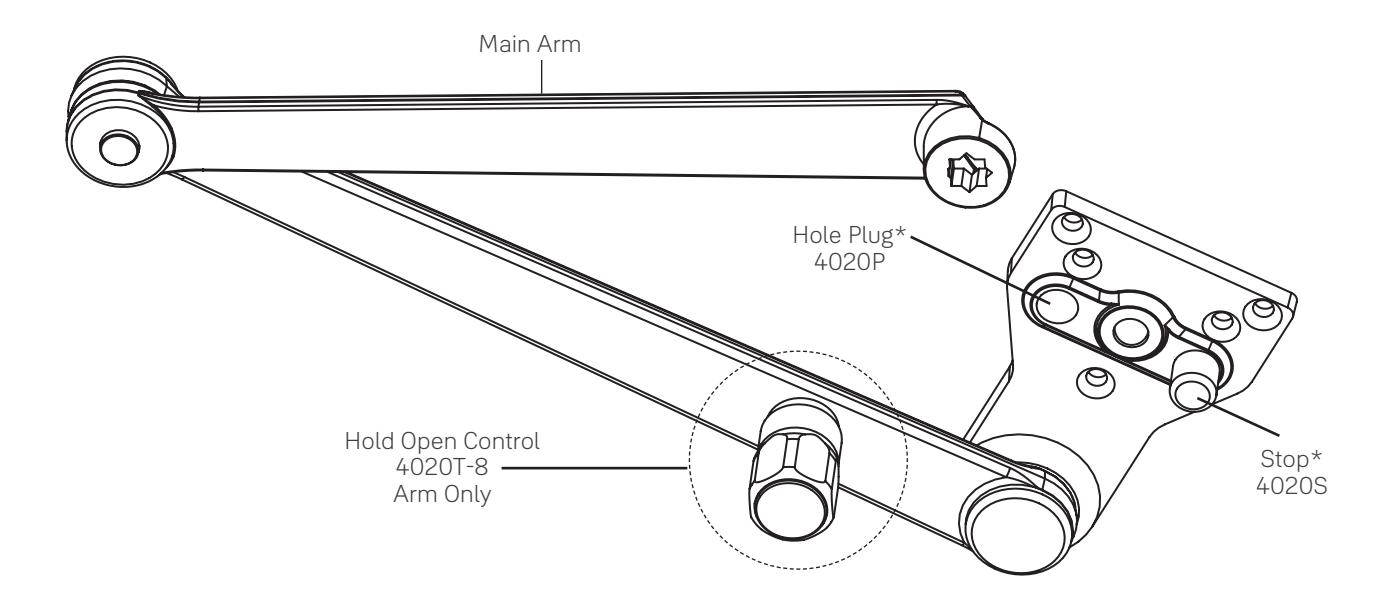
| Arm Function | Complete Arm Package |
|---|---|
| Non-Hold Open | 4020-5 |
| Thumbturn Hold Open | 4020T-8 |
* These parts and screw pack are included with complete arm assemblies.

Holder/Stop Spring Arm Assemblies
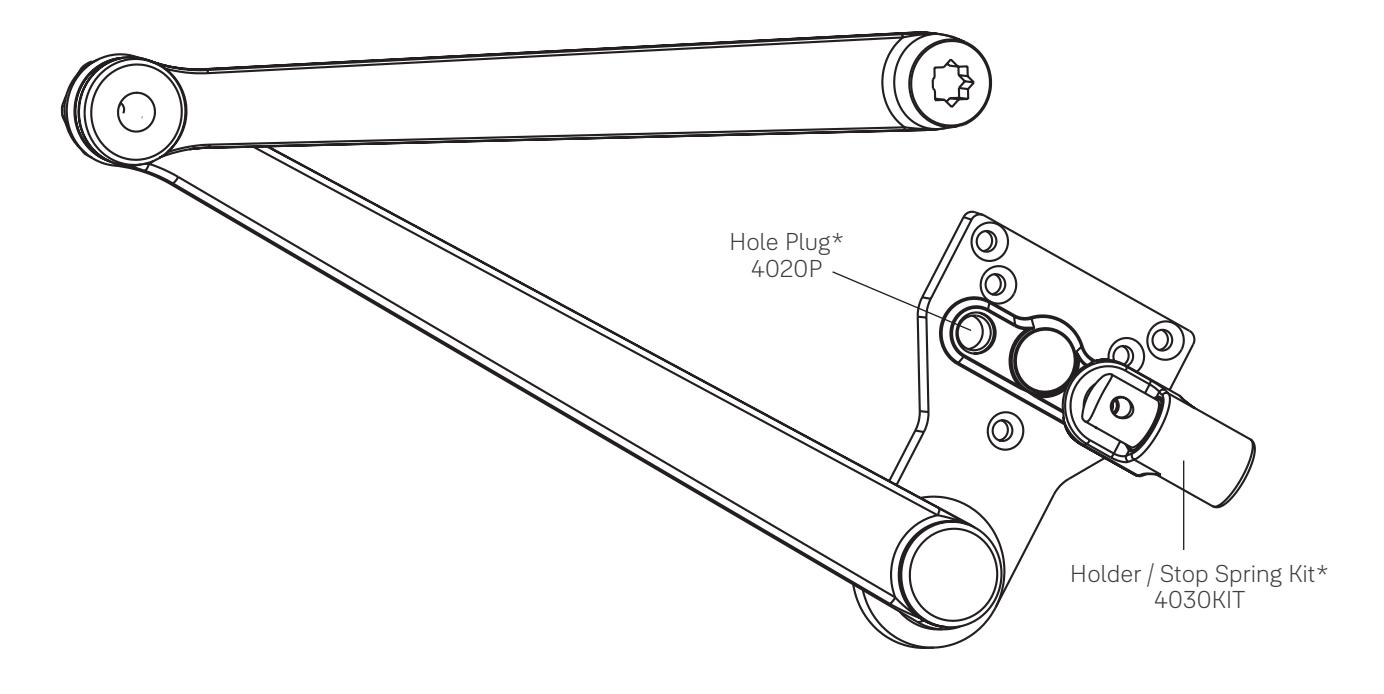
| Arm Function | Complete Arm Package |
|---|---|
| Non-Hold Open | 4030-5 |
| Thumbturn Hold Open | 4030T-8 |
* These parts and screw pack are included with complete arm assemblies.

UNI Stop™ Arm Assemblies
Parallel Arm
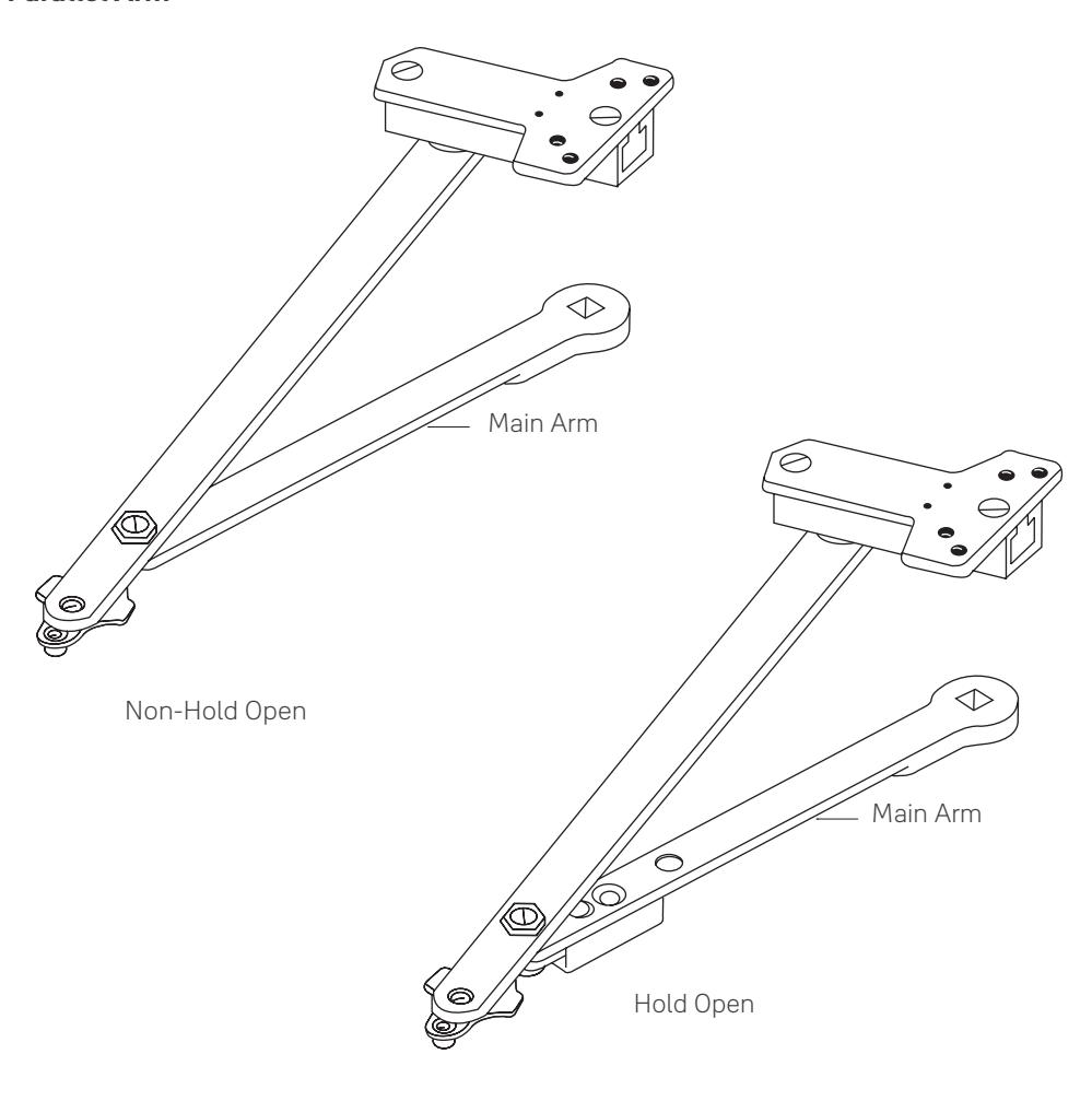
Note: Mounting hardware included with all parts orders.
| Complete Arm Assembly | ||||
|---|---|---|---|---|
| Door Width (cm) |
Main Arm Length*
(mm) |
Non-Hold Open | Hold Open | |
|
28" - 32"
(71- 81) |
9-1/2" (241) | 6100-11 | 6100-1 | |
|
33"- 41"
(84 - 104) |
11" (279) | 6100-13 | 6100-3 | |
|
42" - 48"
(107 - 122) |
12-1/2" (318) | 6100-14 | 6100-4 | |
Only available in painted finishes.

UNI Stop™ Arm Assemblies
Top Jamb

Note: Mounting hardware included with all parts orders.
| Complete Arm Assembly | For Frame Reveals | ||
|---|---|---|---|
| Non-Hold Open | Hold Open | (mm) | |
| J6100-4 | J6100-7 | 2-1/8" - 3-1/4" (54 - 83) | |
| J6200-4 | J6200-7 | 1/2" - 2" (13 - 51) | |
| J6400-4 | J6400-7 | 3-3/8" - 4-1/4" (86 - 108) | |
| J6500-41 | J6500-71 | 4-3/8" - 5-3/8" (111 - 137) | |
| J6500-42 | J6500-72 | 5-1/2" - 6-3/8" (140 - 162) | |
| J6500-43 | J6500-73 | 6-1/2" - 7-3/8" (165 - 187) | |
| J6600-4 | J6600-7 | 0 - 3/8" ( 0 - 10) | |
Only available in painted finishes.

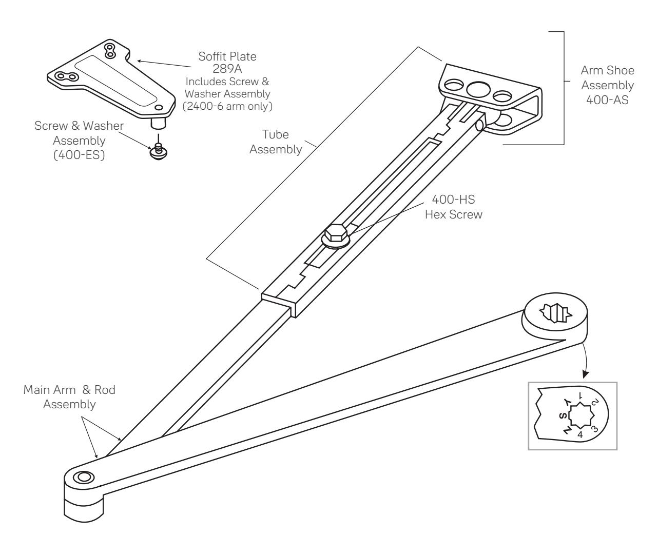
Low Profile Arm Assemblies
| Arm Application |
Complete Arm
Assembly |
Main Arm & Adjusting
Rod Assembly |
Tube & Shoe/Soffit Assembly |
|---|---|---|---|
| Regular Arm | 2400-1 | 2400-1TS (With 400-AS) | |
| Parallel Arm | 2400-6 | 2400-1MR | |
|
Tri-Packed®
Packaging |
2400-26 | 2400-6TS (With 289A) |
Suggested Specification

3301/3501Series
Closers for interior and exterior doors shall be full rackand-pinion type with cast aluminum alloy shell. Closers shall be surface mounted and shall project no more than 2-1/8" from the surface of the door with standard cover. Closers shall be non-handed to permit installation on doors of either hand. Closer fluid shall contain lubricity and anti-oxidation agents. Closer fluid shall maintain stable viscosity to allow door closer to perform in temperatures ranging from extremely high to as low as -40°F. Closers shall have multi-size spring power adjustment to permit setting of spring from size 1 through size 6. Closers shall have two non-critical valves, hex key adjusted, to independently regulate sweep speed and latch speed. Closers shall have adjustable backcheck intensity controlled by a hex key adjusted valve.
[Closers shall have adjustable delayed action closing controlled by a hex key adjustable valve.]
Regular arm and top jamb closers shall have a nonhold open shoe permitting 15% ( + or – 7-1/2% ) power adjustment. **Closers shall be enclosed in a [molded resin cover] [plated or sprayed metal cover], Closers to be Yale® [3301/3501] [3501M] [3501MA] [3501A].
**For special arms insert that specification here (see column three on this page).
**UNI Stop™ Arm
Door closers shall have a fixed door stop feature effective at one point selected at installation, from 85° - 110° in five-degree increments. Door stop shall be cushioned by a shock-absorbing heavy-duty spring action effective at the [soffit plate] [arm shoe] pivot. [Closers shall be provided for parallel arm installation using a rigid steel main arm and secondary arm lengths proportional to the door width.] [Closers shall be provided for top jamb installation using a forged steel, rigid main arm and telescoping secondary arm adequate for the frame reveal of the openings.]
**Holder/Stop Arm
Door closers shall have a field reversible door stop. Door closer shall have a feature with selectable on and off ball and detent hold open. Hold open tension shall be adjustable effective at one point selected at installation, from 85° - 110° in five degree increments. [Hold open mechanism shall have engage/disengage selection actuated by thumbturn]. Closers shall be provided for parallel arm installation using a forged rigid steel main arm and secondary arm.
**Holder/Stop Spring Arm
Door closers shall have built-in door stop [and holder] effective at one point selected at installation, from 85° - 110° in five-degree increments. Door stop mechanism shall be reversible and have a buffer spring that engages prior to the dead stop feature, reducing shock loads to the door and frame assembly. Door stop mechanism shall be non-handed and attached to soffit plate. [Hold open mechanism shall have engage/disengage selection actuated by thumbturn]. Closers shall be provided for parallel installation using a forged rigid steel main arm and secondary arm.

Trusted every day
Phone
1-855-557-5078
Customer Service Email
customerservice.yale@assaabloy.com
Technical Product Support Email
techsupport.yale@assaabloy.com
Order Entry Email
orders.yaleus@assaabloy.com
Fax
1-800-338-0965
Website
www.yalecommercial.com
Contact Us
U.S.A.
Yale Locks & Hardware
Address: 225 Episcopal Road Berlin, CT 06037-4004 Tel: 1-800-438-1951 Fax: 1-800-338-0965 yalecommercial.com
Canada:
ASSA ABLOY Door Security Solutions Canada
Address: 160 Four Valley Drive Vaughan, Ontario L4K 4T9 Tel: 1-800-461-3007 Fax: 1-800-461-8989 assaabloydss.ca
International:
ASSA ABLOY Americas International
Tel: 1-905-821-7775 Fax: 1-905-821-1429 assaabloyai.com
THE YALE BRAND , with its unparalleled global reach and range of products, reassures more people in more countries than any other consumer locking solution.
THE ASSA ABLOY GROUP is the world´s leading manufacturer and supplier of locking solutions, dedicated to satisfying end-user needs for security, safety and convenience.
Yale Commercial is a business associated with ASSA ABLOY Access and Egress Hardware Group, Inc., an ASSA ABLOY Group company. Copyright © 2001-2024, ASSA ABLOY Access and Egress Hardware Group, Inc. All rights reserved. Reproduction in whole or in part without the express written permission of ASSA ABLOY Access and Egress Hardware Group, Inc. is prohibited. Patent pending and/or patent www.assaabloydss.com/patents.
Part of ASSA ABLOY 42072-01/24