ASSA ABLOY ACCENTRA 1900 Series Door Closers Catalog_42066
Open the original PDF document
View PDF

1900 Series Traditional Door Closers

Introduction

Contents
| Introduction 2 |
|---|
| Features & Benefits 3-4 |
| Finishes 5 |
| How to Order 6 |
| Applications 7-8 |
| Technical Details 9-12 |
| Accessories 13-18 |
| Parts List 19-23 |
| Specifications 24 |
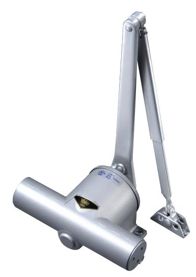
1900 Series Door Closer
The Yale® 1900 Series Traditional Surface Closer offers conventional closer styling in combination with contemporary closer control and the installation convenience of a one-size closer shell. Only two spring sizes are required to provide control for the complete range of door sizes. The 1900 Series Door Closers are designed for traditional and period decor while at the same time meeting the strict requirements of engineers worldwide.
The Yale® 1900 Series Traditional Closers are available for standard arm, parallel arm or corner bracket installation. Rigid heavy-duty non-hold open and hold open arms are available for Parallel Rigid and UNI Stop™ Parallel arm installations. A variety of accessories is available to meet most installation requirements. Yale Works for YouSM.
Features & Benefits

Standard Features
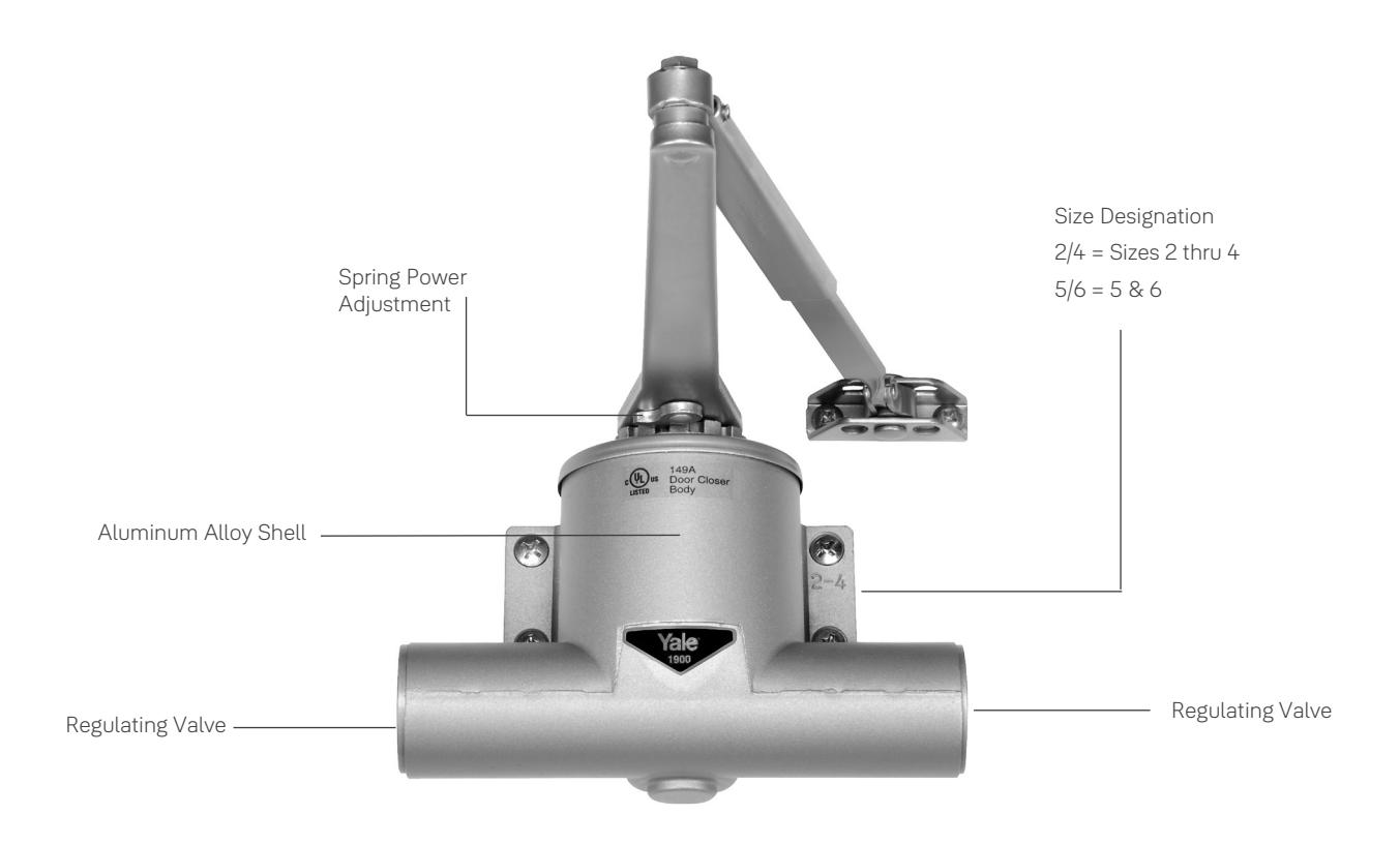
- Choice of adjustable spring power. Models 1902/4 are sizes 2, 3 or 4. Models 1905/6 are sizes 5 and 6
- Heavy-duty arms available
- Handed (closer spring can be reversed in field; recommend ordering correct handing when possible)
Benefits
- Customizable: Available with standard or heavy duty arms to meet installation requirements
- Convenient: One-size closer shell; Only two spring sizes needed to provide control for all door sizes
- Compliant: All closers with non-hold open arms are UL listed for labeled fire doors; UL10C compliant
Compliance Standards
- UL/cUL listed for use on fire rated doors
- UL10c listed for positive pressure fire test
- This product is manufactured in an ISO 9001, ISO 14001 facility.
Features

One-Size Aluminum Housing
Closer is housed in special aluminum alloy shell selected for its ability to provide optimum performance. One body size provides simplified templating and installation.
Adjustable Spring Power
Clock-type coil spring allows incremental adjustment of closer power to meet individual installation needs. Permits a fine adjustment of the closer to the environment.
Rack and Pinion Design
Provides a smooth constant control of the door through its full opening and closing cycle.
Adjustable Closing Speed/Latch Speed
A dual-purpose regulating valve, hex-key operated, permits independent adjustment of both sweep and latch speed.
Adjustable Backcheck Cushioning
An independent regulating valve, hex-key-operated, provides an adjustable hydraulic cushion to the door opening speed toward the end of the opening cycle. This feature is standard with all but delayed action closers. Backcheck is not available with delayed action closers.
Non-Hold Open Arm
Standard closer will be supplied with a non-hold open arm. This arm is non-handed.
Optional Features
Adjustable Delayed Action Closing*
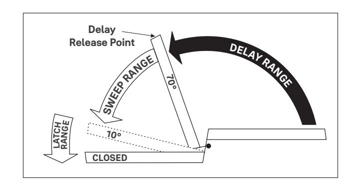
(Supplied in lieu of backcheck feature) An optional hydraulic feature that adds a third speed range to the closing cycle. This feature becomes effective when the door is opened and released at any point beyond 70°. The amount of time delay depends upon the combination of the angle of door release and valve adjustment. The valve can be adjusted with a 1/8" (3mm) hex key from no delay time up to maximum delay times of:
Suggested Applications
Delayed action closing allows slow-moving traffic to clear the opening before the door closer's normal closing cycle begins. This feature can be helpful in health care facilities such as hospitals and nursing homes. It provides sufficient time for persons on crutches or in wheelchairs to pass through a door without concern of it closing. At the same time, it can accommodate the facility's staff with movement of food service carts, beds, and other wheeled traffic. Use of delayed action closers on many doors throughout industrial and commercial buildings can also assist the flow of traffic. Locations where additional time to clear the opening is advantageous are doors between office and factory/warehouse facilities, doors to workshops or laboratories, to kitchen and food processing areas, etc.
Adjustable Power Standard Installation Jamb Bracket
Provides a ±7-1/2% power adjustment by relocation of the forearm pin in the jamb bracket. Supplied standard with all standard installation and corner bracket installation non-hold open closers.
Hold Open Arm
Available with heavy-duty arms (Parallel Rigid and UNI Stop)
Field Reversible
Closer spring can be reversed to accommodate the hand of the door. It is recommended that wherever possible the closer be ordered handed.
Adjustable Delayed Action Closing
Closer's initial closing speed at the beginning of the closing cycle (from full open down to approximately 70°) is adjustable, allowing slow-moving traffic to pass through the opening before the closer begins its normal closing speed. For regular arm nonhold open closers only. Delayed action closers are not available with backcheck cushioning. Delayed action closers are handed.
|
Door Opened and
Released at |
Approximate Time
of Delay Cycle |
|---|---|
| 180° | 4-5 minutes |
| 120° | 2-3 minutes |
| 90° | 25-30 seconds |
* Note: Regular arm (NHO units only) are handed - not reversible
Finishes

Product will be painted with a combination of waterborne acrylic and polyester powder coat. Closers will withstand 100 hours of salt spray. (The ANSI requirement is 25 hours.)
|
ANSI/BHMA Code
Finish Description |
|||
|---|---|---|---|
|
600*
Primed for Painting |
689
Aluminim Painted |
690
Dark Bronze Painted |
691
Light Bronze Painted |
|
693
Black Painted |
694
Medium Bronze Painted |
696
Satin Brass Painted |
|
*600 is a special rust-inhibiting prime coat. Closers can be ordered prime coat only (specify closer x 600). An additional charge applies if finish coat is required over prime coat (ex: 1902/4 x 600 x 689).
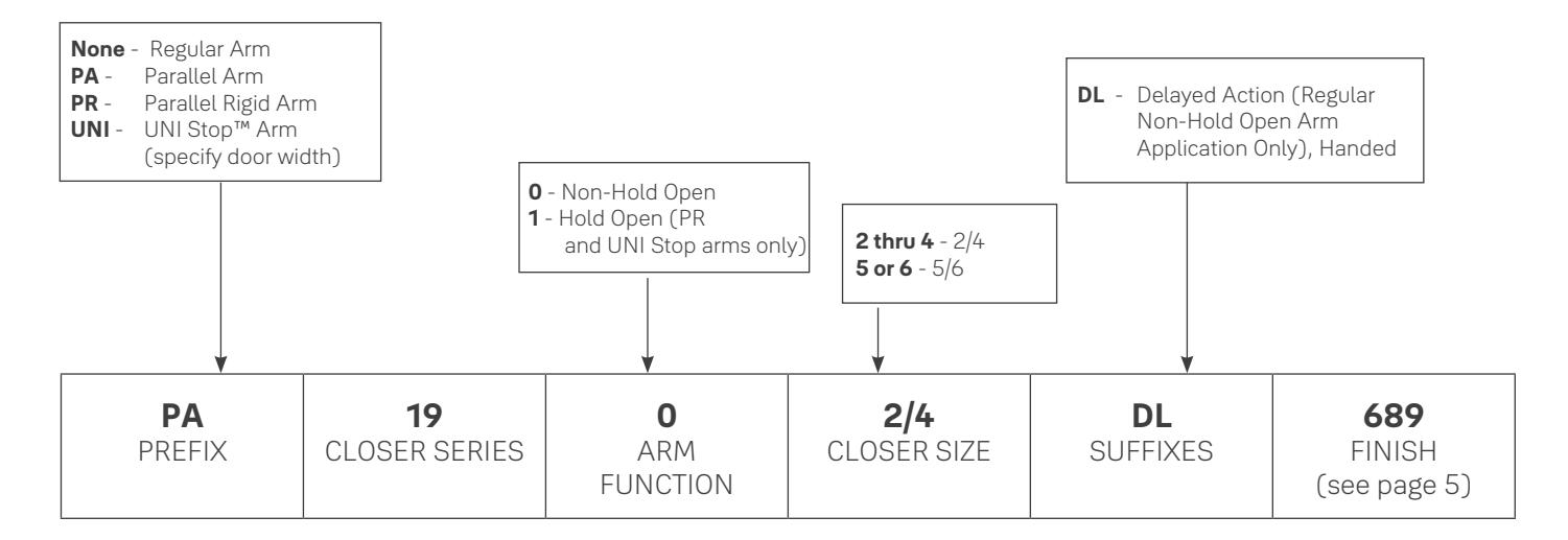
How To Order

NOTE:
- Before installing a door closer, verify the accessibility, fire, and life-safety requirements that are in effect. This includes the mounting height and projection into the clear opening. Check the adopted state and local building codes and consult the Authority Having Jurisdiction (AHJ).
- To maintain the warranty and ensure proper operation of the product, follow the installation instructions & templates and install on the inside of the building.
- Consult NFPA 80 for the hinge requirements on a fire door.
- Failure to use fasteners supplied with closer may void factory warranty.
- Optional fasteners are available for a variety of applications. Consult the door and frame manufacturer to ensure the proper fasteners are used to maintain certifications.
- Sizing charts are based on 1-3/4" x 7' standard weight doors swinging to 110°. Other application conditions (i.e. larger door heights or weight) may require larger size closer. Adjusting the spring power to meet the low opening force requirements of the Americans With Disabilities Act or ANSI/BHMA Standard A117.1, may not provide adequate closing power to dependably close and latch the door in some conditions (i.e. air movement from wind gusts or building stack pressure).
Applications

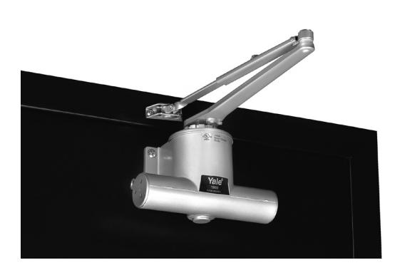
Regular Arm
This is the only pull-side application where a double lever arm is used. It is the most power-efficient application for a door closer. Sufficient frame, door and/or ceiling clearance must be considered. Since the arm assembly projects directly out from the frame, this application may present an aesthetics issue or be prone to vandalism.
Only available with non-hold open arm.
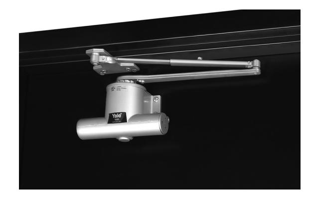
Parallel Arm
This application provides the most appealing design appearance for a surface-mounted door closer having a double lever arm. This also makes it beneficial in vandalism-prone areas. It is on the push side of the door and the arm assembly extends almost parallel to the door. In the closed position, there is very little or no hardware projecting beyond the frame face in most situations.
Due to the geometry of the arm it is approximately 25% less power-efficient than a regular arm application.
The entire closer and arm assembly are mounted below the frame stop, requiring a top rail of 5-3/8" (137mm) to mount the body. Clearance to the bottom of the closer body from the top of the door is 7-3/8" (187mm). (Based on a 5/8" (16mm) high frame stop.)
Only available with non-hold open arm.
Applications

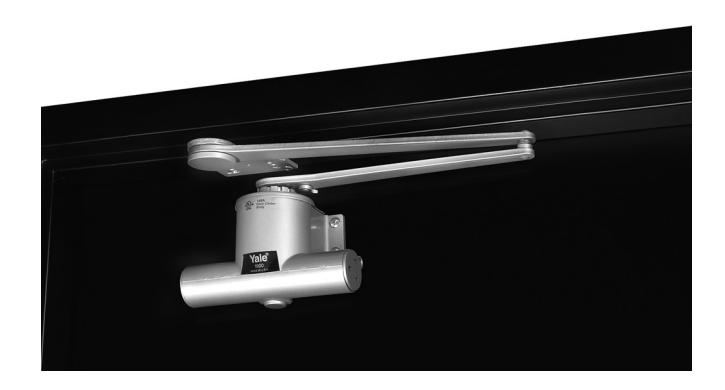
Parallel Rigid Arm
An enhanced variation of the standard parallel arm assembly that is intended for use in heavy traffic areas where auxiliary door stops are installed. Hold open available - specify hand when ordering.
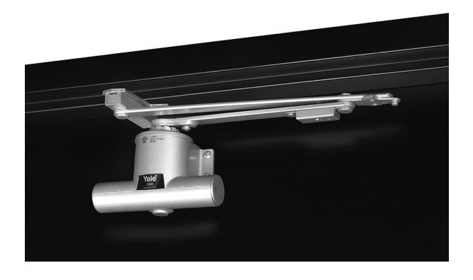
UNI Stop™ Arm (Parallel Arm applications only)
UNI Stop™ arms combine the features of a double-lever arm overhead door stop/holder with the backcheck feature of the door closer to reduce door stopping shock loads to a minimum. The UNI Stop arm uses a compression spring buffer at the soffit plate/arm shoe that will absorb 30 lbs. of force, 5° prior to the door's dead stop. Coupled with the door closer's backcheck feature, this arm provides the most controlled stop available with a surface door closer.
There are three different length arm assemblies. Each length is designed for a specific range of door widths to provide precise door control. This further lessens the dead stop impact on the door's hinges/pivots.
Regular Arm Installation

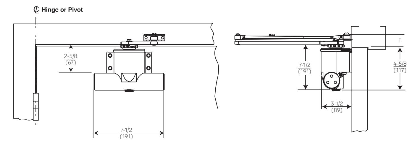
Body mounting holes are spaced 4-1/8" (105mm) horizontally and 1-3/8" (76mm) vertically.
|
Maximum Door Size
Wood or Metal Inches (cm) |
Model Number |
E
Minimum Ceiling Clearance Inches (mm) |
|
|---|---|---|---|
| Interior | Exterior |
Non-Hold
Open |
Non-Hold
Open |
|
48"
(122) |
36"
(91) |
1902/4 | 1-1/2" |
| — |
44"
(112) |
1905/6 | (38) |
Dimensions are given in inches (mm) unless otherwise noted. All dimensions are for reference only.
Parallel Arm Installation

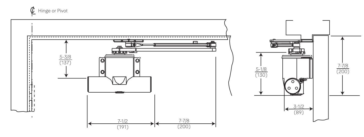
Body mounting holes are spaced 4-1/8" (105mm) horizontally and 1-3/8" (76mm) vertically.
|
Maximum Door Size
Wood or Metal Inches (cm) |
Model Number | |
|---|---|---|
| Interior | Exterior |
Non-Hold
Open |
|
42"
(107) |
36"
(91) |
PA1902/4 |
| — |
44"
(112) |
PA1905/6 |
All dimensions are for reference only. Dimensions are given in inches (mm) unless otherwise noted.
Parallel Rigid Arm

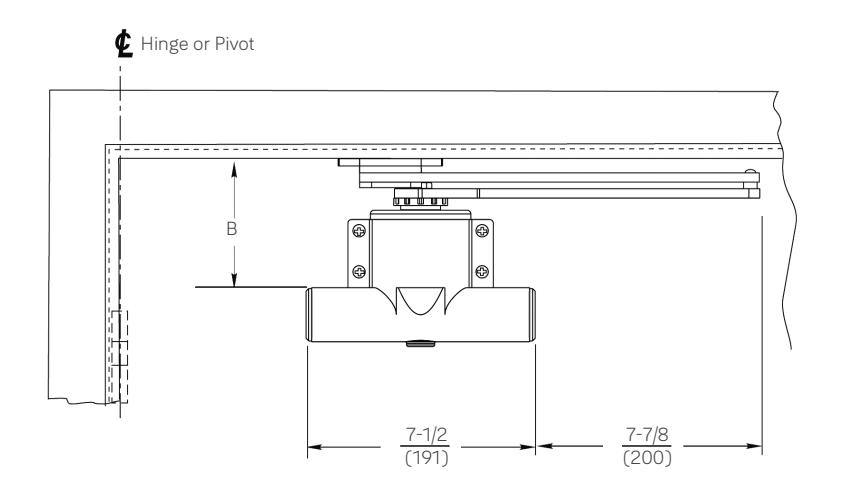
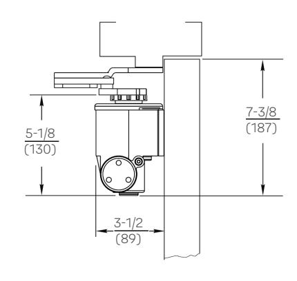
Body mounting holes are spaced 4-1/8" (105mm) horizontally and 1-3/8" (76mm) vertically.
|
Maximum Door Size
Wood or Metal Inches (cm) |
Model Number |
B
Minimum Top Rail with 5/8" (16mm) frame stop |
||||
|---|---|---|---|---|---|---|
| Interior | Exterior | Non-Hold Open |
Hold
Open |
Without
Drop Plate |
With 1988
Drop Plate |
|
|
48"
(122) |
36"
(91) |
PR1902/4 | PR1912/4 | 5-3/8" | 2-1/2" | |
| — |
44"
(112) |
PR1905/6 | PR1915/6 | (137) | (64) | |
All dimensions are for reference only. Dimensions are given in inches (mm) unless otherwise noted.
UNI™ Stop Arm

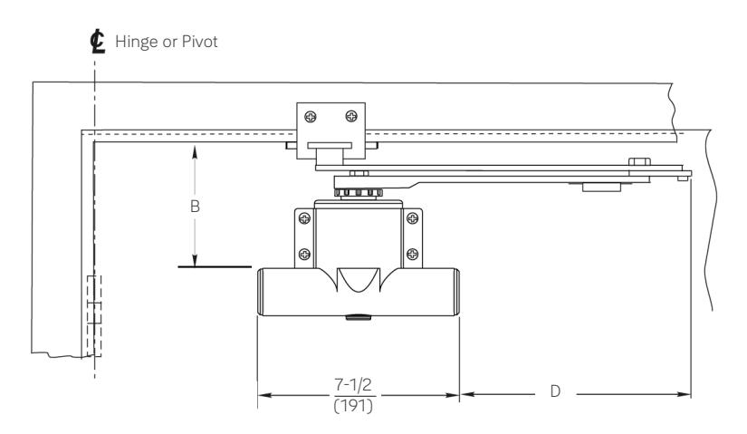
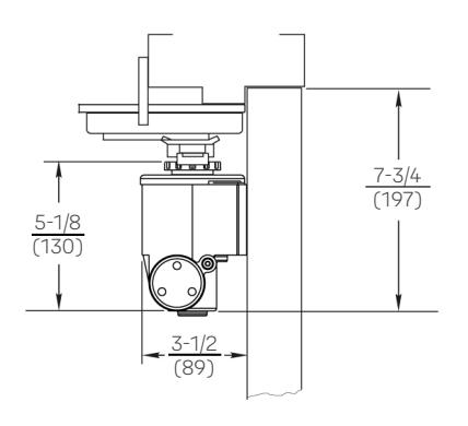
Body mounting holes are spaced 4-1/8" (105mm) horizontally and 1-3/8" (76mm) vertically.
|
Door Width
Inches |
l
Minimun 5/8" (16mm |
D
Arm |
|
|---|---|---|---|
| (cm) |
Without
Drop Plate |
With 1988 Drop
Plate |
Extension
Beyond Closer |
|
28-32"
(71-81) |
8-7/8"
(225) |
||
|
33-41"
(84-104) |
5-5/8"
(143) |
2-3/4"
(70) |
10-3/8"
(264) |
|
42-48"
(107-122) |
11-7/8"
(302) |
|
n Door Size
s (cm) |
Model Number | |||
|---|---|---|---|---|
| Interior | Exterior |
Non-Hold
Open |
Hold
Open |
|
|
28-41"
(71-104) |
28-36"
(71-91) |
UNI1902/4 | UNI1912/4 | x Specify Door Width |
|
42-48"
(107-122) |
37-48"
(94-122) |
UNI1905/6 | UNI1915/6 |
All dimensions are for reference only. Dimensions are given in inches (mm) unless otherwise noted.
Regular Arm

Brackets For Non-Hold Open Arms
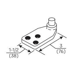
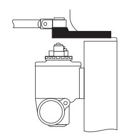
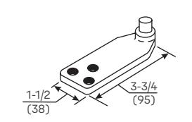
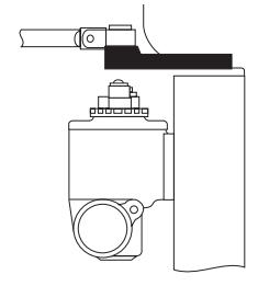
Molded/Bull Nose Trim - 291 Bracket:
For use where the door frame has molded or bull nose trim which will not accept a standard non-hold open shoe. The bracket is mortised into the frame rabbet and projects beyond the face of the frame. It will accommodate a frame rabbet up to 2" (51 mm) deep.
Molded/Bull Nose Trim - 291A Bracket:
This bracket is similar to - but longer than - the 291 bracket. It is designed to accommodate frame rabbets from 2" to 2-7/8" (51 to 73mm) deep.
Bracket For Hold Open Arms
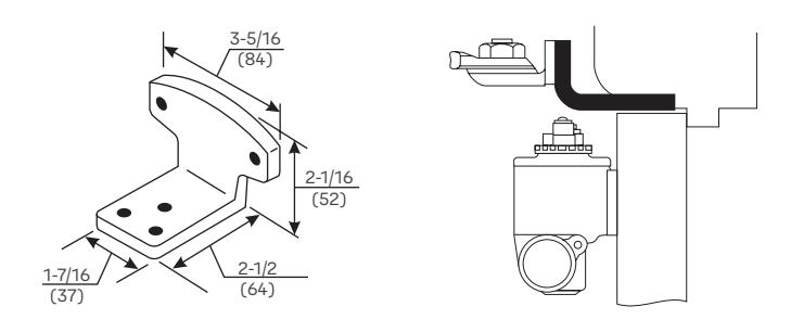
Molded/Bull Nose Trim - 292 Bracket: For use where the door frame has molded or bull nose trim which will not accept a standard hold open shoe. It is mortised into the frame rabbet, and projects beyond the face of the frame. It will accommodate a rabbet up to 2" (51mm) deep. This bracket is used in combination with the standard hold open mounting shoe.
Parallel Arm

Brackets For Non-Hold Open Arms
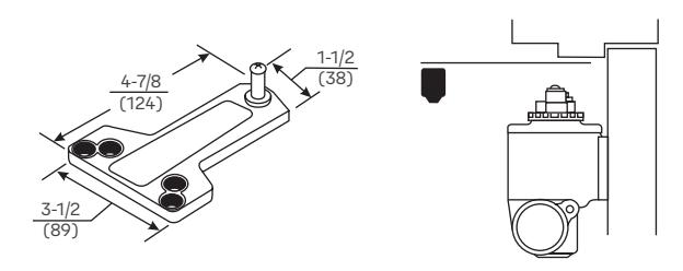

This soffit plate is supplied standard with parallel arm closers. It can be mounted where the frame soffit is as narrow as 1" (25mm).
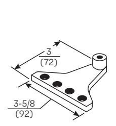
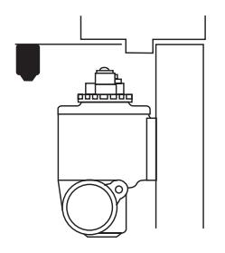
Narrow Frame/Removable Stop - 297 Soffit Plate: For use where a narrow frame or frame with removable stop does not permit use of the standard soffit plate. This plate may be mounted on the frame soffit or the frame rabbet where the stop does not exceed 5/8" (16mm) in height. All of the screw holes are in a straight line, requiring as little as 1-1/4" (32mm) of frame reveal to mount bracket and maintain good closer arm geometry. Where the frame soffit is as wide as 2" (51mm), this soffit plate may be used to clear weatherstripping that is up to 1-3/8" (35mm) wide and 5/8" (16mm) in height.
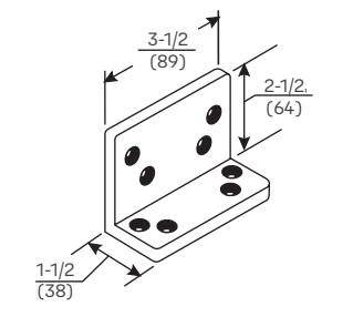
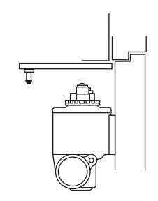
Flush Transom - 589L Angle Bracket: For use where rabbeted or flush transom conditions prevent installation of a soffit plate. Used in combination with the 289 soffit plate, or it may be used in combination with the 290 soffit plate when it is necessary for the closer arm to clear a separate overhead door holder.
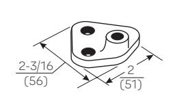
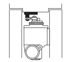
Mounting Between Doors - 413A Soffit Bracket: For use where insufficient space between companion doors does not permit use of other soffit plates. This bracket permits mounting of the closer between doors with as little as 4-1/8" (105mm) of header space. Permits closer arm to clear up to a 5/8" (16mm) high stop.
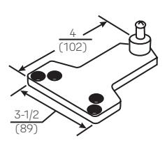
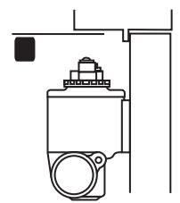
Blade/Applied Stop - 299 Soffit Plate: For use where a blade or applied stop does not permit installation of the standard soffit plate. Mounts to either the frame soffit or rabbet. Since this soffit plate projects 7/8" (22mm) less than a standard soffit plate, it requires a minimum frame reveal of 1-1/2" (38mm). Permits closer arm to clear up to a 5/8" (16mm) high stop.
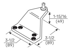
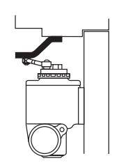
Extra-Clearance - 290 Offset Soffit Plate: For use where the need for additional clearance prevents use of the standard soffit plate. This plate mounts to the frame soffit to provide up to 1-1/2" (38mm) of clearance when a separate overhead door holder is used. Standard mounting requires a 2-5/8" (67mm) wide frame soffit. It may also be used where unusually high frame stops or weatherstripping prevents the use of other soffit plates.
Parallel Rigid Arm

Brackets For Non-Hold Open And Hold Open Arms
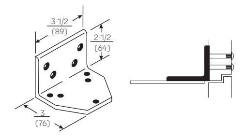
Flush Transom - 293L Angle Bracket: For use where flush transom conditions prevent installation of the standard hold open soffit plate. Used for parallel hold open arms.
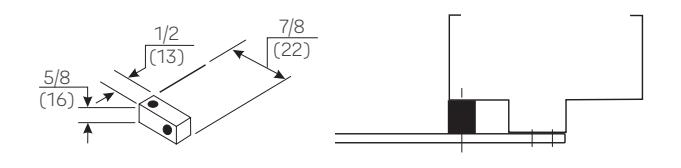
Standard - 293S Spacer Block: For use where a narrow frame soffit does not provide adequate support for the soffit plate. Supplied as standard with all rigid parallel arm closers.
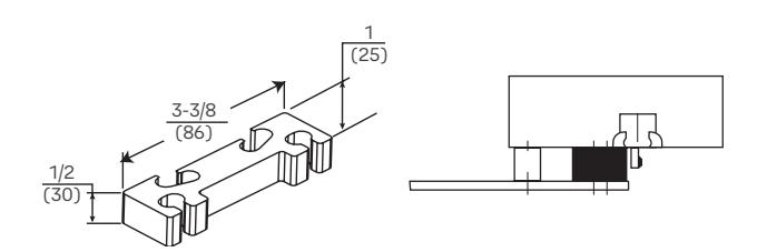
Clearance/Support Blade Stop - 891 Spacer Block: For use where the frame has a blade stop and the soffit plate must be mounted on the frame rabbet. This accessory is used in combination with the standard Spacer Block to provide clearance of the blade stop.
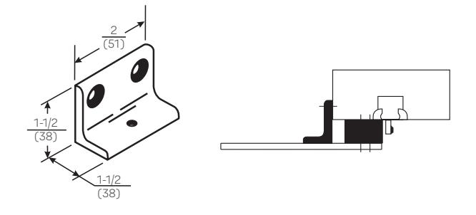
Narrow Frame - 890 Support Bracket: For use where the frame is narrow, and the soffit plate cannot be mounted directly to the frame soffit or rabbet. Used in combination with the 891 Spacer Block on blade stop frames to provide extra support and needed clearance of the blade stop.
Closer Mounting Plates
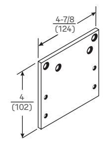
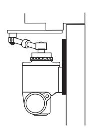
Narrow Top Rail - 1988 Drop Plate: For use where a narrow top rail prevents the closer from being mounted directly to the door surface.
UNI Stop™ Arm

Brackets
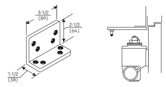
Flush Transom - 589L Angle Bracket: For use where rabbeted or flush transom conditions prevent installation of a soffit plate. Used in combination with the 289 soffit plate, or it may be used in combination with the 290 soffit plate when it is necessary for the closer arm to clear a separate overhead door holder.
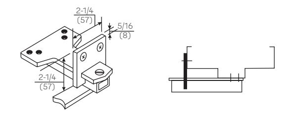
Additional Support - 6190 Reinforcing Bracket: Standard for use with all parallel arm door controls. Provides additional support to the soffit plate on installations with door frame reveals from 1-7/8" to 4-5/8" (48 to 117mm).
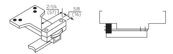
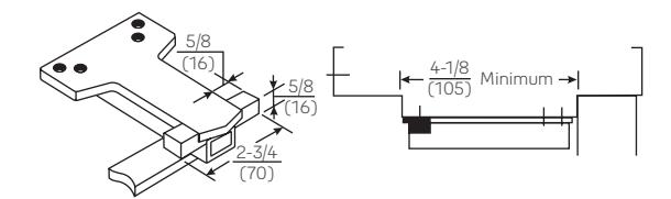
Wide Frame - 6191 Reinforcing Kit: Optional for use with all parallel arm UNI Stop door controls. Used to support the soffit plate on installations with wide frames. Clamps may be used with or without the spacer block, depending on frame conditions.
Closer Mounting Plates
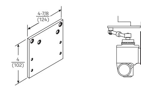
Narrow Top Rail - 1988 Drop Plate: For use where a narrow top rail prevents the closer from being mounted directly to the door surface.
Corner Brackets

The following frame-mounted brackets, 1950, 2950 and 964, require the use of a door closer of the opposite hand from the hand of the door. Use the Parallel Arm Sizing Chart to select the correct size of closer to use, when the closer is to be mounted on a corner bracket.
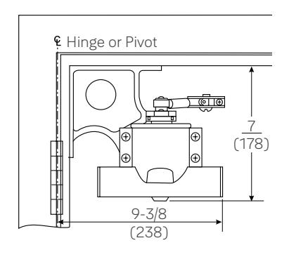
Corner Mounting, Standard Drop - 1950 Corner Bracket: For use where door is required to open to 180°. Minimum soffit width 1-3/8" (35mm).
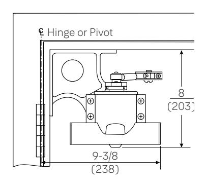
Corner Mounting, Extra Drop - 2950 Corner Bracket: For use with a separate overhead door holder. Drops closer 1" (25mm) lower than 1950 Standard Drop Corner Bracket to permit mounting of an overhead holder. Permits door openings to 180°. Minimum soffit width 1-3/8" (35mm).
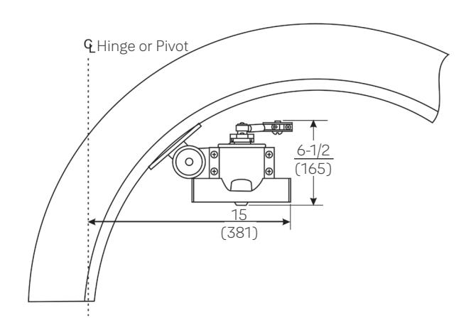
Arched or Circular Top Door - 964 Adjustable Bracket:
For opposite hinge side application on arched or circular top doors. This frame-mounted bracket can be adjusted to accommodate virtually any radius of frame. Minimum soffit width 2-1/2" (64mm). This bracket requires the use of a door closer of the opposite hand from that of the door. Intended for 90° swing.
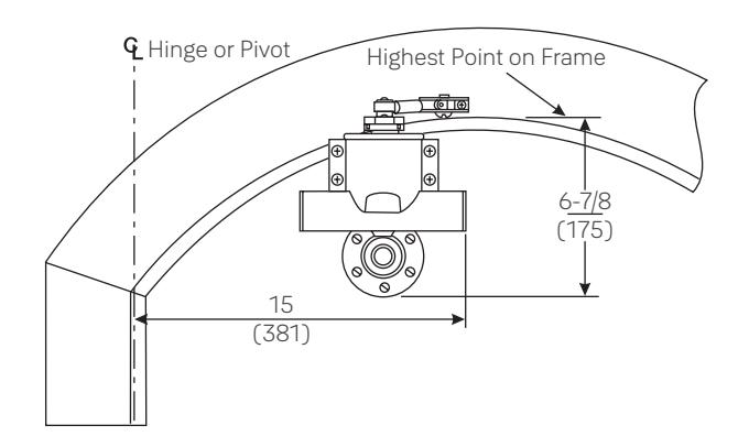
Arched or Circular Top Door - 974 Offset Adjustable
Bracket: For hinge side application on arched or circular top doors. This door-mounted bracket is adjustable to accommodate virtually any radius of frame. Base diameter 3-5/8" (92mm). Intended for 90° swing.
Adapter Plates

| Size Closer |
Adapter Plate
Catalog Number |
Dimensions | |
|---|---|---|---|
| Being Replaced | A | B | |
| 992/993 | 1983 |
5-1/2"
(140) |
2-5/8"
(67) |
| 994 |
None
Required |
— | — |
| 995/996 | 1986 |
5-1/2"
(140) |
2-5/8"
(67) |
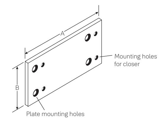
1980 Series Adapter Plate
For use when replacing a discontinued old style 990 Series surface closer with a series 1900 Traditional Surface Closer. The plate selected will employ the existing holes in either door or corner bracket. The Series 1900 closer will mount to the plate. These plates can be used to convert regular arm, parallel arm or bracket mount installations. Order by model number.

Regular Arm
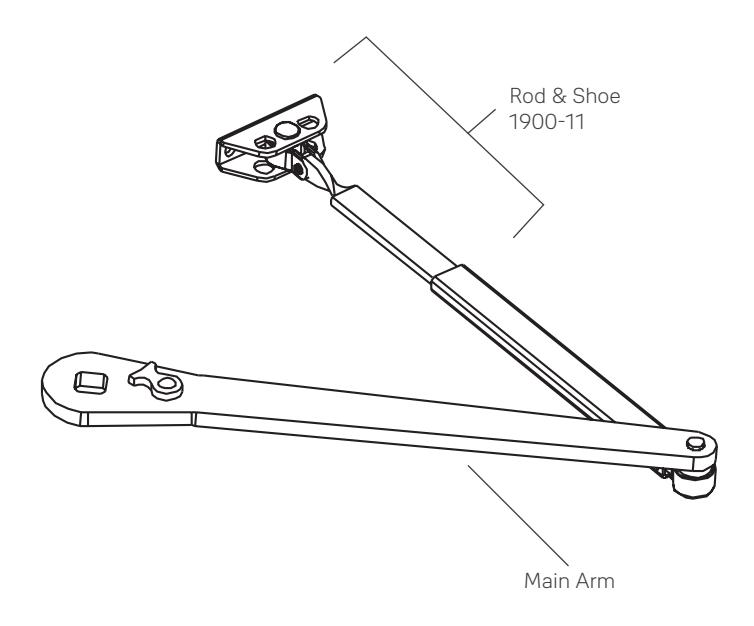
Note: Mounting hardware included with all parts ordered
| Arm Function | Complete Arm Assembly | Main Arm |
Main Arm
Less Rod & Shoe |
|---|---|---|---|
| Non-Hold Open | Y1900-1 | 1900-1M | Y1900-1W |

Parallel Arm
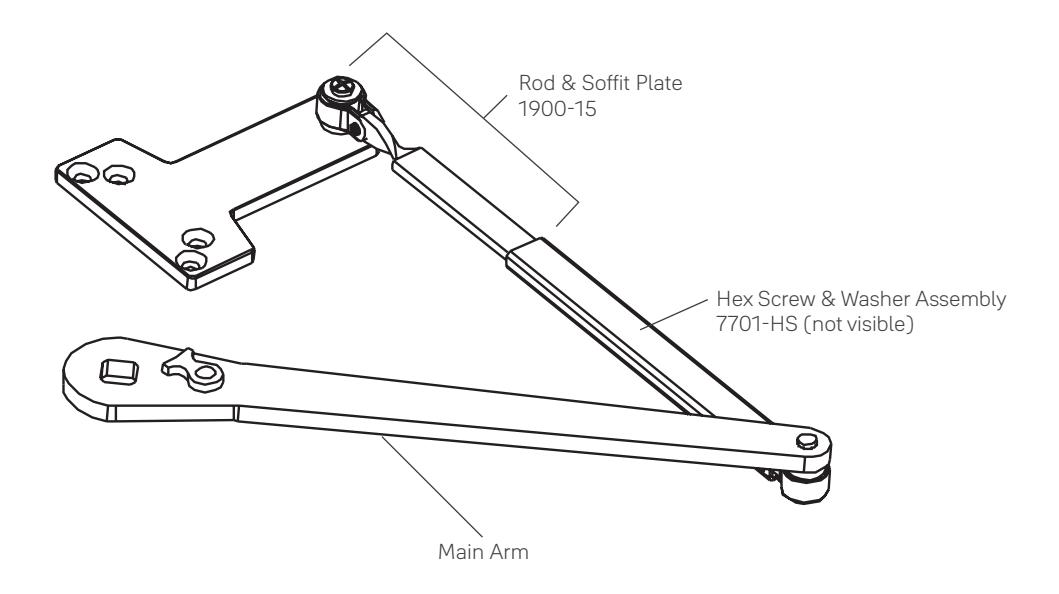
Note: Mounting hardware included with all parts ordered
| Arm Function | Complete Arm Assembly | Main Arm |
Main Arm Less
Rod & Soffit Plate |
|---|---|---|---|
| Non-Hold Open | Y1900-5 | 1900-1M | Y1900-1W |

Parallel Rigid Arm Assemblies
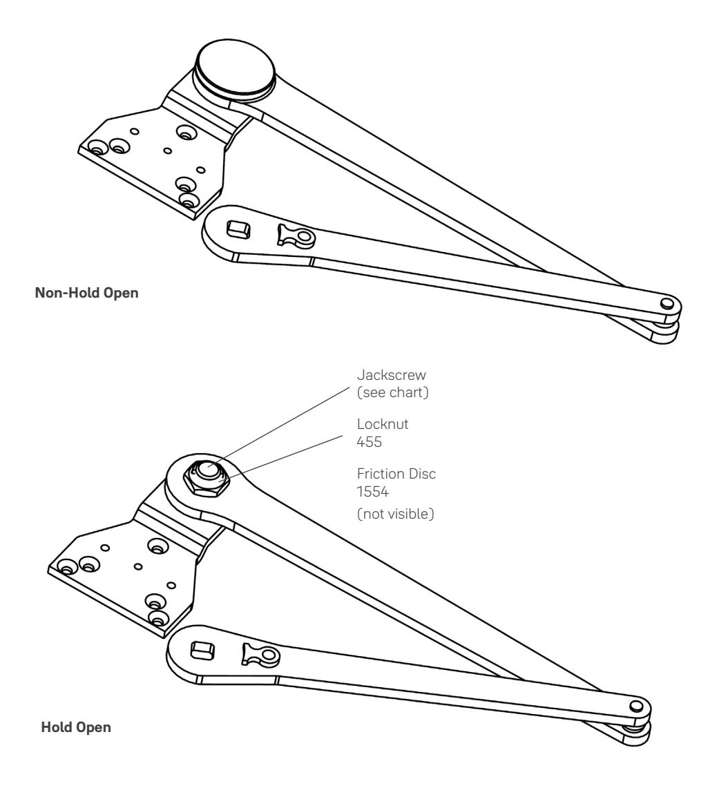
Note: Mounting hardware included with all parts ordered
| Arm Function | Complete Arm Assembly | Jackscrew |
|---|---|---|
| Non-Hold Open | PR1900-5 | N/A |
| PR1900-8R (Right Hand) | 1543R | |
| Hold Open | PR1900-8L (Left Hand) | 1543L |

UNI Stop™ Arm Assemblies
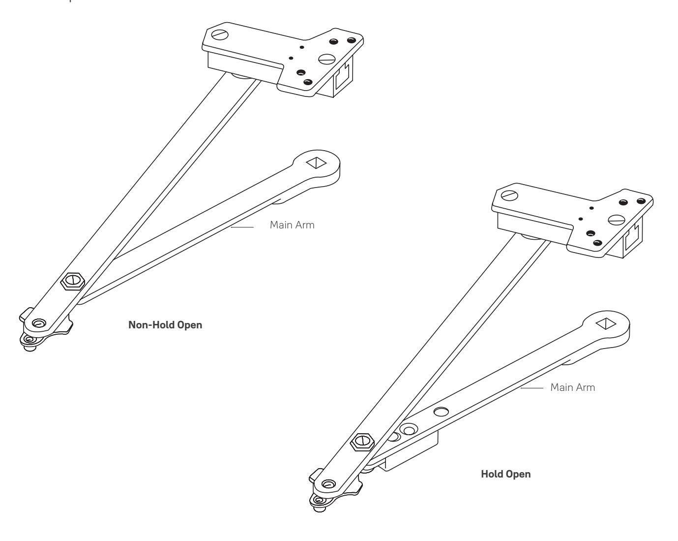
Note: Mounting hardware included with all parts ordered
| Door Width |
Main Arm
Length* (mm) |
Complete Arm Assembly | |
|---|---|---|---|
| (cm) | Non-Hold Open | Hold Open | |
|
28"- 32"
(71 - 81) |
9-1/2"
(241) |
6130-17 | 6130-7 |
|
33"- 41"
(84 - 104) |
11"
(279) |
6130-18 | 6130-8 |
|
42"- 48"
(107 - 122) |
12-1/2"
(318) |
6130-19 | 6130-9 |
* Center to center length

Miscellaneous Parts
| Springs | |
|---|---|
| 24BD | B/D Spring |
| 56EF | E/F Spring |
| Closer Bodies | |||||
|---|---|---|---|---|---|
| 1902/4 LAP | Size 2-4 body | ||||
| 1905/6 LAP | Size 5/6 body | ||||
Screw Packs
| Sex Nuts | |||||
|---|---|---|---|---|---|
| SN-134 | 1-3/4" door | ||||
| SN-214 | 2-1/4" door | ||||
| Thru Bolts & Grommet Nuts | |||||
|---|---|---|---|---|---|
| TBGN138-38 | 1-3/8" door | ||||
| TBGN134-38 | 1-3/4" door | ||||
| TBGN214-38 | 2-1/4" door | ||||
Fasteners
|
Type
Description |
Arm | ||||||
|---|---|---|---|---|---|---|---|
| RA | PA | PR | UNI STOP™ | ||||
| DOOR | |||||||
| SDST | Self-Drilling Self-Tapping | S | S | S | S | ||
| MS | Machine Screw | S | S | S | S | ||
| SN | Sleeve Nut | O | O | S | S | ||
| TBGN | Thru Bolts & Grommet Nuts | O | O | O | O | ||
| FRAME | |||||||
| SDST | Self-Drilling Self-Tapping | S | S | S | S | ||
| MS | Machine Screw | S | S | S | S | ||
S = standard; O = optional
SN are for use on unreinforced hollow metal doors or to prevent any hollow metal door from collapse/dimpling. They can also be used for thru bolting on wood doors. SN are supplied for 1-3/4" (44mm) thick doors unless specified for 2-1/4" (57mm).
TBGN are an alternative to SN for wood doors. TBGN are supplied standard for 1-3/4" (44mm) thick doors. They can be specified for 1-3/8" (35mm) thick doors.
Specifications

Closer for interior (and) exterior doors shall be rack-and-pinion type enclosed in a cast aluminum alloy shell. Closer spring shall be clock-type coil spring and shall be adjustable through a range of closing power. Closer fluid shall maintain lubricity and contain anti-oxidation agents. Closer shall be equipped with a single hex-key operated regulating valve for control of both closing and latch speeds. Closer shall have adjustable backcheck. Closer shall be Yale® 1900 Series Traditional Surface Closer or equivalent.
Notes


Trusted every day
Phone
1-855-557-5078
Customer Service Email
customerservice.yale@assaabloy.com
Technical Product Support Email
techsupport.yale@assaabloy.com
Order Entry Email
orders.yaleus@assaabloy.com
Fax
1-800-338-0965
Website
www.yalecommercial.com
Contact Us
U.S.A.
Yale Locks & Hardware
Address: 225 Episcopal Road Berlin, CT 06037-4004 Tel: 1-800-438-1951 Fax: 1-800-338-0965 yalecommercial.com
Canada:
ASSA ABLOY Door Security Solutions Canada
Address: 160 Four Valley Drive Vaughan, Ontario L4K 4T9 Tel: 1-800-461-3007 Fax: 1-800-461-8989 assaabloydss.ca
International:
ASSA ABLOY Americas International
Tel: 1-905-821-7775 Fax: 1-905-821-1429 assaabloyai.com
THE YALE BRAND , with its unparalleled global reach and range of products, reassures more people in more countries than any other consumer locking solution.
THE ASSA ABLOY GROUP is the world´s leading manufacturer and supplier of locking solutions, dedicated to satisfying end-user needs for security, safety and convenience.
Yale Commercial is a business associated with ASSA ABLOY Access and Egress Hardware Group, Inc., an ASSA ABLOY Group company. Copyright © 2001-2024, ASSA ABLOY Access and Egress Hardware Group, Inc. All rights reserved. Reproduction in whole or in part without the express written permission of ASSA ABLOY Access and Egress Hardware Group, Inc. is prohibited. Patent pending and/or patent www.assaabloydss.com/patents.
Part of ASSA ABLOY 42066-01/24