ASSA ABLOY ACCENTRA 150 Series Regular, Top Jamb or Parallel Arms, Hold Open Installation_80-9350-3504-010
Open the original PDF document
View PDF150 Series Door Closer Model 151
ACCENTRA
Regular, Top Jamb, and Parallel Arms, Hold Open Installation Instructions

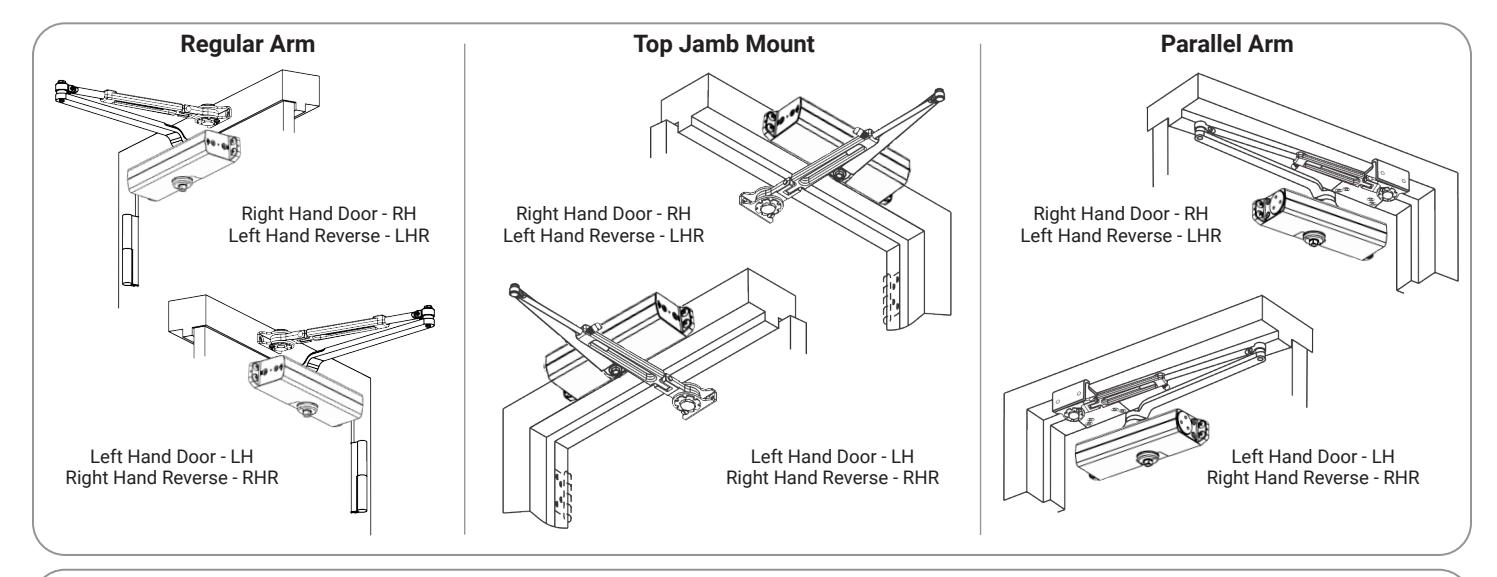
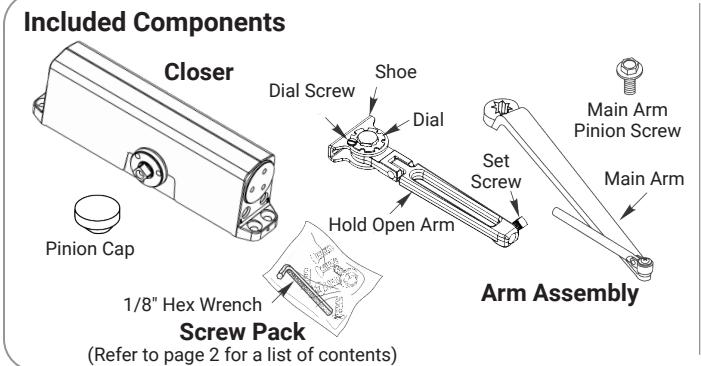
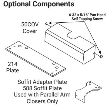
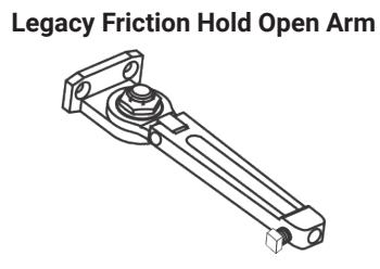
NOTE: Legacy FHO arm has installation orientation. Refer to document number 80-9300-0003-000 for details.
WARNING
This product can expose you to lead which is known to the state of California to cause cancer and birth defects or other reproductive harm. For more information go to www.P65warnings.ca.gov.
✓ WARNING
Attention Installer: Any retrofit or other field modification to a fire rated opening can potentially impact the fire rating of the opening, and ASSA ABLOY makes no representations or warranties concerning what such impact may be in any specific situation. When retrofitting any portion of an existing fire-rated opening, or specifying and installing a new fire-rated opening, please consult with a code specialist or local code official (Authority Having Jurisdiction) to ensure compliance with all applicable codes and ratings.
Model 151 Regular, Top Jamb, and Parallel Arms, Hold Open
ASSA ABLO
ATTENTION:
An incorrectly installed or improperly adjusted door closer can cause property damage or personal injury. These installation instructions should be followed to avoid the possibility of misapplication or misadjustment.
- For special applications, a separate door and frame preparation template is packed with these instructions. Use this instruction sheet for installation sequence and closer adjustments only.
- Doors should be hung on ball bearing or anti-friction hinges.
- · A separate door stop is recommended.
- · Always consult door/frame manufacturer for fastener compatibility.
- Door and frame must be properly reinforced.
- Adjust closing time speed between 3 and 7 seconds from 90° to 0°.
- These door closers should NOT be installed on exposed side (weather side) of exterior doors.
- Dimensions are given in inches (millimeters).
Supplied Hardware
| Mounting Hardware | Door or Frame | Drill | |
|---|---|---|---|
| Closer, Holder Shoe, Holder, PA Bracket: 1/4-14 x 1-1/2 Oval Flat Head Self Drilling. Screw | 3/16" (4.8mm) for wood | ||
|
Closer, Holder Shoe, Holder, PA Bracket:
1/4-20 x 3/4 Oval Flat Head Mach. Screw |
Metal |
Drill #7 (.201 dia. or 5.1mm)
Tap 1/4-20 |
|
| H/O Shoe to Holder, PA Bracket: 1/4-20 x 1/2 Oval Flat Head Mach. Screw | All | N/A | |
|
Closer:
Sleeve Nut and Bolt (SNB) (optional) with 1/4-20 x 3/4 Oval Flat Head Mach. Screw (recommended) |
Hollow Metal |
9/32" (7.0mm) thru
3/8" (9.5mm) door face opposite to closer |
|
| Aluminum or Wood | 3/8" (9.5mm) thru | ||
| Decemberations | Closer: Thru Bolt and Grommet Nut (TBGN) (optional) |
9/32" (7.0mm) thru
3/8" (9.5mm) dia. x 3/8" (9.5mm) deep, door face opposite to closer |
|
Closer Adjustments

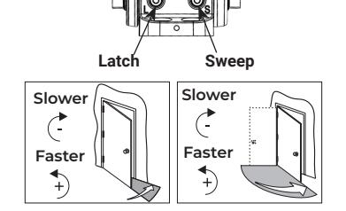
Use provided hex wrench to turn valves. NEVER force valves out of closer. NEVER completely close backcheck valve. Door must be open to adjust spring closing power. Refer to the chart.

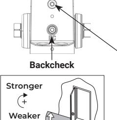
| heck | ١, |
|---|---|
| , | |
| 7 |
| Spring Closing Power | Number of Turns Required | |||||||
|---|---|---|---|---|---|---|---|---|
| ٦ | Type of | Maximum Door Size | ||||||
| Door | Installation | * |
34"
(0.85M) |
36"
(0.90M) |
40"
(1.00M) |
44"
(1.10M) |
48"
(1.20M) |
|
| 151 | Interior |
Regular Arm
Top Jamb |
Full 360° Turns | 2 | 4 | 6 | 10 | 12 |
| Parallel Arm | 3 | 5 | 8 | 11 | 14 | |||
| Exterior |
Regular Arm
Top Jamb |
3 | 5 | 8 | 11 | 14 | ||
| Ä | Parallel Arm | 5 | 8 | 11 | 16 | 19 | ||
| *30 Full (360°) turns maximum available = turns as shipped | ||||||||
Pinion Cap or Cover

Do not over tighten cap or cover screws.
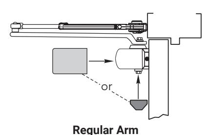
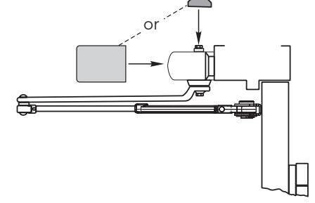
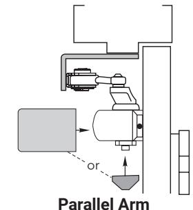
Top Jamb Mount
Experience a safer and more open world
Regular Arm Installation (Right Hand Shown)
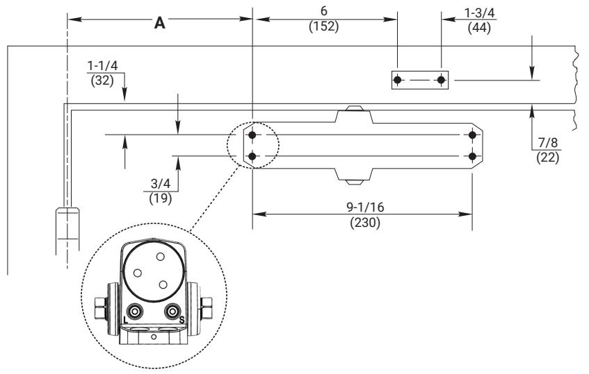
A. Prepare door and frame.
| Opening | Dimension "A" | ||
|---|---|---|---|
| to 100° | 7 (178) | ||
| 101° to 120° | 6 (152) | ||
| *121° to 180° | 3-1/2 (89) | ||
| *Door/Wall/Hardware/Jamb conditions permitting | |||
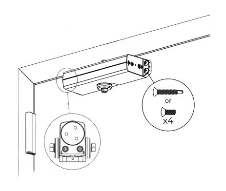
B. Mount closer to door.

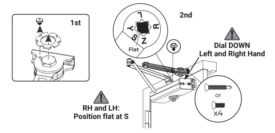
D. Connect arms, preload spring, and tighten set screw.
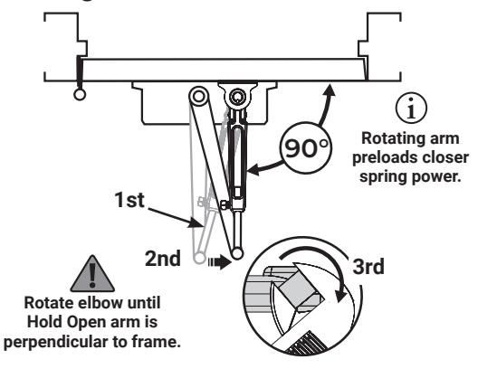
E. Set Hold Open.
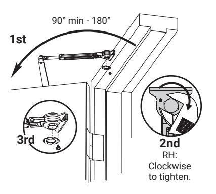
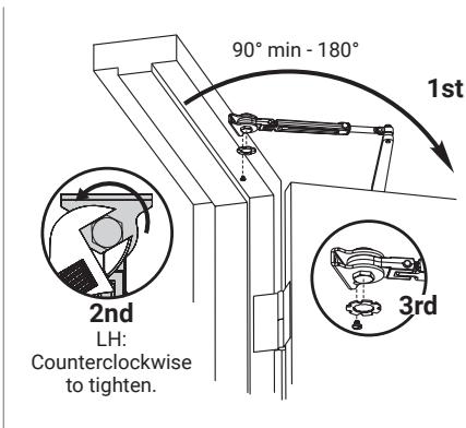
Keep door open in position until dial screw secures dial.
Go to page 2 for closer adjustments and decorative cap or cover installation.
Model 151
Regular, Top Jamb, and Parallel Arms, Hold Open
Top Jamb Arm Installation (Right Hand Shown)
A. Prepare door and frame.
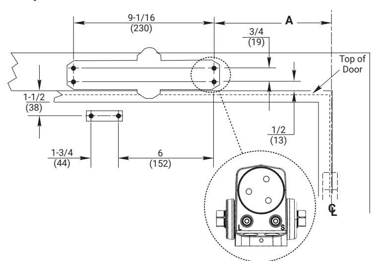
| Opening | Dimension "A" | ||
|---|---|---|---|
| to 100° | 7-1/2 (191) | ||
| 101° to 120° | 6 (152) | ||
|
*121° to 180°
3-1/2 (89) |
|||
| *Door/Wall/Hardware/Jamb conditions permitting | |||
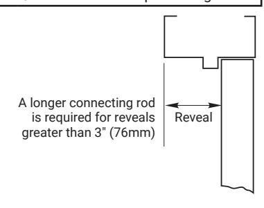
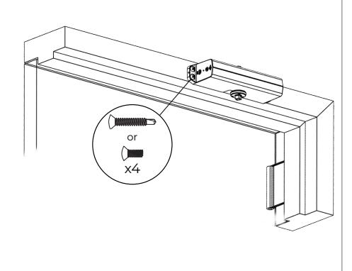
B. Mount closer to frame.
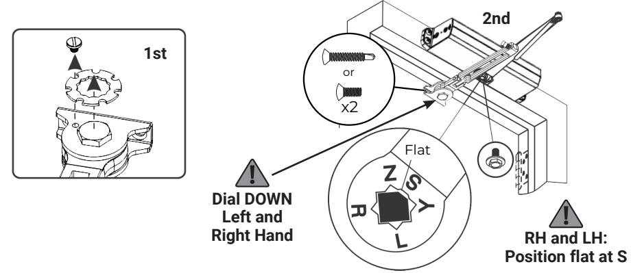
C. Remove dial from Hold Open arm and install separate arms.
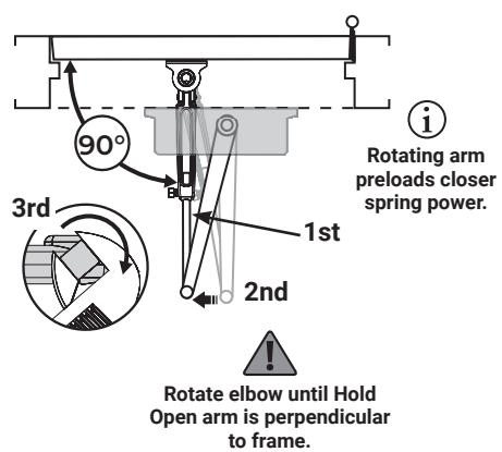
D. Connect arms, preload spring, and tighten set screw.
E. Set Hold Open.
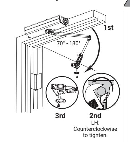
Keep door open in position until dial screw secures dial.
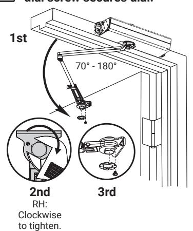
Go to page 2 for closer adjustments and decorative cap or cover installation.
Model 151
Regular, Top Jamb, and Parallel Arms, Hold Open
Parallel Arm Installation (Right Hand Shown)
A. Prepare door and frame.
|
Door
Opening |
Dimension
"A" |
Dimension
"B" |
Dimension
"C" |
||
|---|---|---|---|---|---|
| to 100° | 9-1/4 (235) | 7-5/8 (194) | 8-5/8 (219) | ||
| 101° to 130° | 7-3/4 (197) | 6-1/8 (156) | 7-1/8 (181) | ||
| *131° to 180° | 5-3/4 (146) | 4-1/8 (105) | 5-1/8 (130) | ||
| *Door/Wall/Hardware/Jamb conditions permitting | |||||
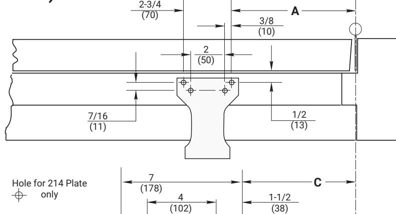
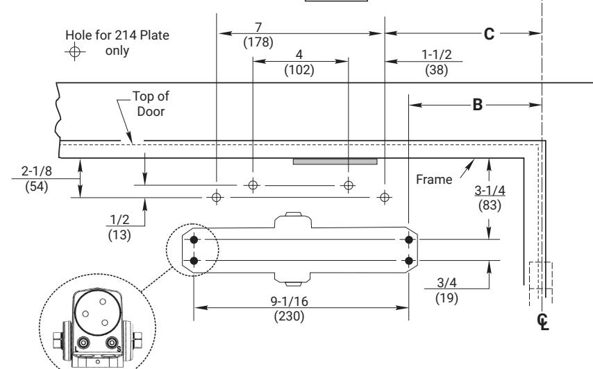
B. Close latch and sweep valves. C. Remove dial from
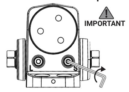
Hold Open arm.
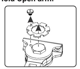
D. Install soffit plate and
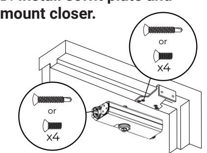
E. Install Hold Open arm to plate.
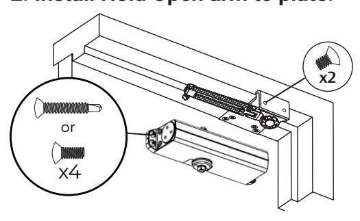
F. Place main arm on closer spindle and rotate.
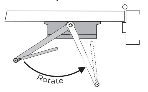

Parallel Arm Installation (Right Hand Shown) cont.
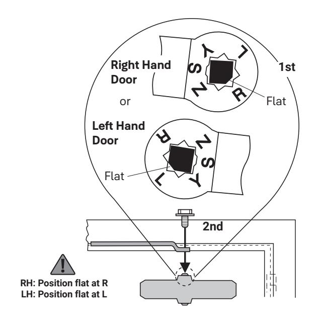
G. Remove arm and attach as shown.
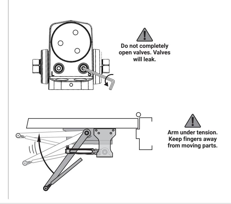
H. Open latch and sweep valves.
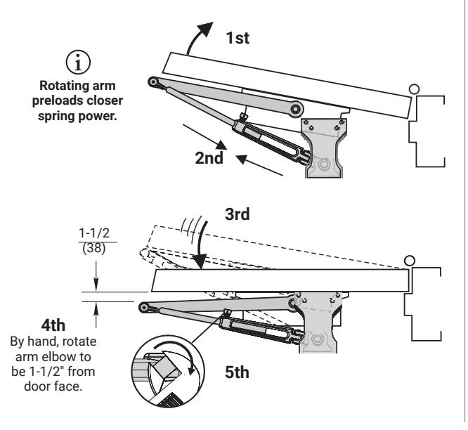
I. Connect arms, preload spring, and tighten set screw.
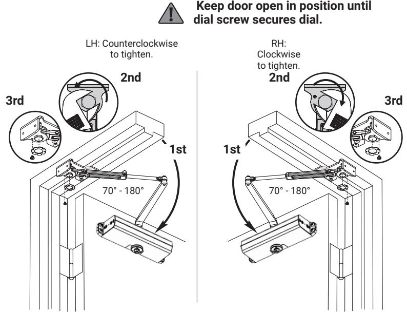
J. Set Hold Open.
Go to page 2 for closer adjustments and decorative cap or cover installation.