ASSA ABLOY ACCENTRA 1104BC Size 4 with Backcheck (for Units Shipped After December 2012_80-9316-8001-000
Open the original PDF document
View PDFINSTALLATION INSTRUCTIONS
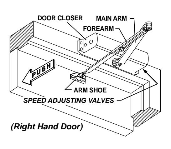
NON-HOLD OPEN ARM
Incorrect installation or adjustment could cause damage or injury. Read and follow instructions carefully.
Power size 4
Option A – Regular Arm Installation
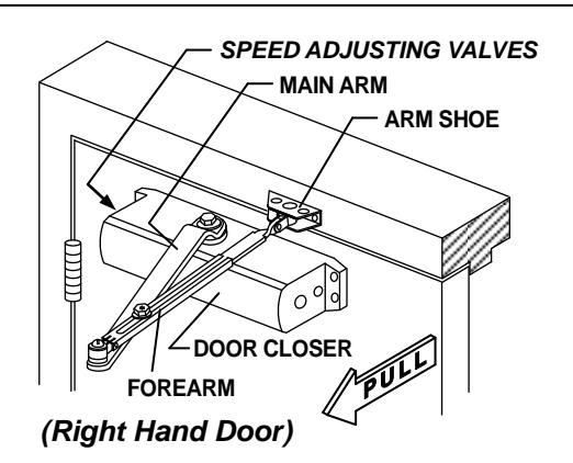
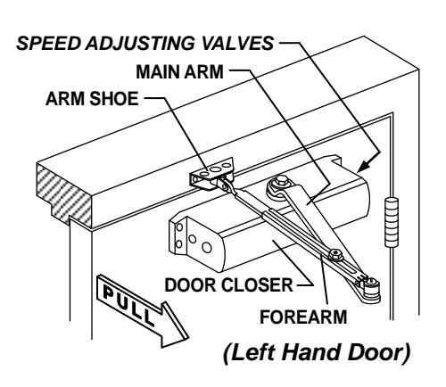
Diagram for Option A
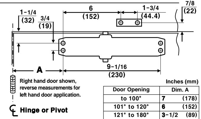
Option A instructions: 1. Using the measurements from diagram A, mark screw hole center locations. Mark four (4) hole locations on door for door closer and two (2) hole locations on frame for arm shoe. 2. Drill pilot holes in door and frame, drill 7/32"(5.5mm) diameter holes for wood screws or drill and tap #7(.201" diameter) for 1/4-20 machine screws. 3. Install adjustable forearm/arm shoe to frame using screws (a) or (b). 4. Mount closer on door using screws (c) or (d). SPEED ADJUSTING VALVES MUST BE POSITIONED TOWARD HINGE SIDE. 5. Install main arm to top pinion shaft, perpendicular to door. Secure tightly with arm screw/washer (e). 6. Adjust length of forearm so it is perpendicular to frame when assembled to preloaded main arm. Secure forearm to main arm with screw/washer (f). 7. Adjust closing speed, see page 2 for reference. 8. Snap pinion cap over shaft at bottom of closer or install (optional) cover with small screw (j).
Option B – Top Jamb Installation
Inches (mm) Door Opening Dim. A Hinge or Pivot to 100° (178) Left hand door shown, 101° to 120° 6 (152)reverse measurements for 121° to 180° 3-1/2 (89) right hand door application. 9-1/16 1 - 1/2(230)(38)Ф 3/4 1-3/4 (13)(152) (44.4)
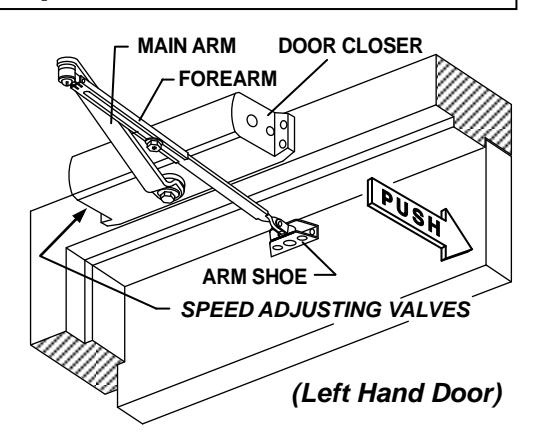
Diagram for Option B
Option B instructions: 1. Using the measurements from diagram B, mark screw hole center locations. Mark four (4) hole locations on door for door closer and two (2) hole locations on frame for arm shoe. 2. Drill pilot holes in door and frame, drill 7/32"(5.5mm) diameter holes for wood screws or drill and tap #7(.201" diameter) for 1/4-20 machine screws. 3. Install adjustable forearm/arm shoe to door using screws (a) or (b). 4. Mount closer on frame using screws (c) or (d). SPEED ADJUSTING VALVES MUST BE POSITIONED TOWARD HINGE SIDE. 5. Install main arm to bottom pinion shaft, perpendicular to door. Secure tightly with arm screw/washer (e). 6. Adjust length of forearm so it is perpendicular to door when assembled to preloaded main arm. Secure forearm to main arm with screw/washer (f). 7. Adjust closing speed, see page 2 for reference. 8. Snap pinion cap over shaft at bottom of closer or install (optional) cover with small screw (j).
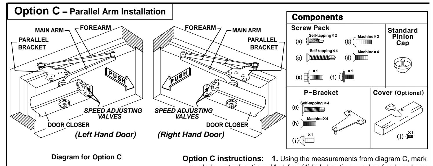
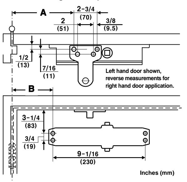
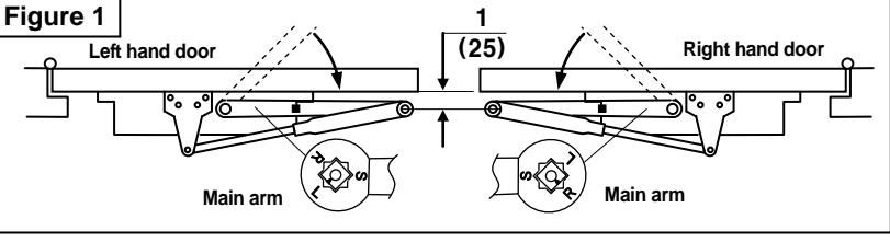
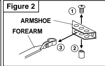
screw hole center locations. Mark four (4) hole locations on door for door closer and four (4) hole locations on inside frame for parallel bracket. 2. Drill pilot holes in door and frame, drill 7/32"(5.5mm) diameter holes for wood screws or drill and tap #7(.201" diameter) for 1/4-20 machine screws. 3. Install Parallel bracket to frame using screws (g) or (h). 4. Mount closer on door using screws (c) or (d). SPEED ADJUSTING VALVES MUST BE POSITIONED AWAY FROM HINGE SIDE. 5. Place main arm on closer pinion shaft. Index main arm - mark "L" or "R" with pinion flat as shown in Figure 1. Secure tightly with screw/washer (e). 6. Remove arm shoe from forearm (see figure 2). Install Parallel bracket to end of forearm using the screw (i). 7. With door closed, adjust length of forearm so that the tip of the main arm is approximately 1" (25mm) away from being parallel with door, when connected to the forearm. Secure with screw/washer (f). 8. Adjust closing speed, see below 9. Snap pinion cap over shaft at bottom of closer or Install (optional) cover with small screw (j).
| Door Opening | Dim. A | Dim. B | ||
|---|---|---|---|---|
| To 100° | 9-1/4 | (235) | 7 -5/8 | (194) |
| 101° to 130° | 7 -3/4 | (197) | 6 -1/8 | (156) |
| 131° to 180° | 5 -3/4 | (146) | 4 -1/8 | (105) |
Left hand door shown, reverse measurements for right hand door application.
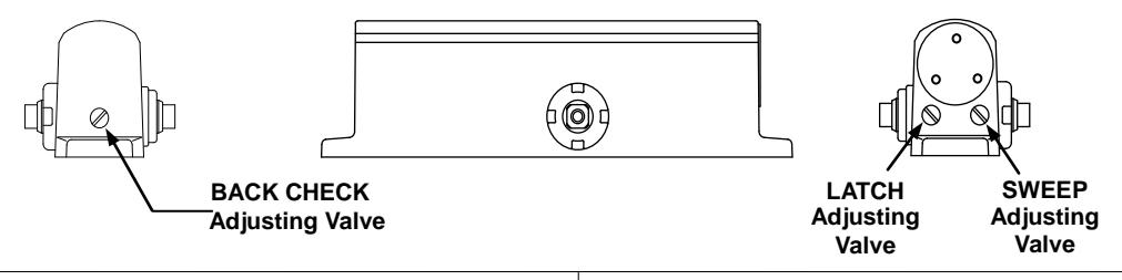
DOOR CLOSER ADJUSTMENT
CAUTION!!
Do not turn speed adjusting valves more than two (2) full turns counter-clockwise. Do not back valves out of closer or a leak will result.
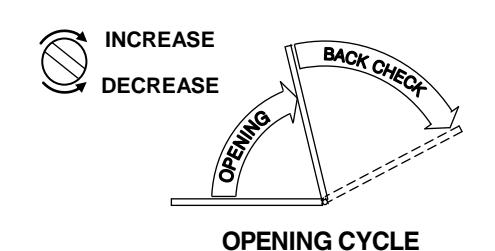
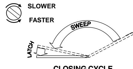
CLOSING CYCLE