ACSI Power Supply Installation Instructions II-1400-05
Open the original PDF document
View PDFACSI MODEL 1420 POWER SUPPLY INSTALLATION INSTRUCTIONS
Features:
- Controls an opening with electrified door hardware and automatic door operator
- Separate inputs for activation switch on entry and exit sides of opening
- Separate 24VDC outputs for fail safe and fail secure electrified door hardware (2 amp max. for either output)
- Relay dry contact output to automatic door operator input
- Input for optional fire alarm or emergency release switch when urgent unlocking of door is required
- Auxiliary 24VDC constant voltage output (1 amp max.)
- Built-in time delay between activation of electrified door hardware and automatic door operator
- Filtered/Regulated 24 Volts DC
- Class 2 Rated Outputs
- Overload, over voltage, and short circuit protection
- Automatically accepts 120VAC or 240VAC input
- UL listed and Tested to 294 Standard for Access Control System Units with Security Levels Rated I for Physical Attack, IV for Endurance, I for Line Security, I for Standby Power
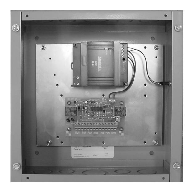
Installing the 1420
The unit must be mounted indoors and away from any moist or wet areas. Some common locations for mounting the 1420 would be in the plenum near the door containing the electrified door hardware, or in a nearby closet or electrical room. When installing the unit in the plenum, wires must either be of plenum rating or contained inside conduit. The unit must be mounted in a vertical position with the power supply module located at the top, as shown in the photograph above. Four 1/4" holes are provided for mounting the box to the wall or other rigid surface. If the surface material is wood, it must be at least 1 inch thick. Use either a truss or pan head, 1 inch long sheet metal screw (#10 or larger) for fastening the box to the wood surface. When mounting the unit to 1/2 inch or 5/8 inch dry wall, it is recommended that 3/16 inch or 1/4 inch diameter toggle bolts be used for maximum support. Use the same size toggle bolts for mounting the unit to hollow concrete blocks. For mounting to concrete, solid block, or brick, it is recommended to use 1-3/4 inch long (minimum) x 1/4 inch diameter hex head bolt
anchors (sometimes called power-bolts) in 18-8 stainless steel or Grade 5 zinc-plated steel. The sub plate can be removed from the box for easier access to the mounting holes. To remove the sub plate, locate the four #6 locknuts near each corner of the plate and remove. The 6-32 studs, from which the sub plate mounts to, are held in place to the box by threaded standoffs.
Wiring the AC Input
The 1420 power supply is rated for use with a 20 amp branch circuit and is capable of accepting either 120VAC or 240VAC input without the need for making any changes, or reconfiguring to convert from one input voltage to the other. Because the power supply module contains Class 2 double insulation, an earth ground wire is not required. For wiring 120VAC or 240VAC input, run 14 AWG 2-conductor to the power supply module's input terminals marked L (Line) and N (Neutral). Ensure that the conductors are fully inserted into the input terminals with no bare metal exposed. (Refer to the wire stripping instructions included on the wiring diagram attached to the cover plate of this power supply.)
CAUTION! It is important to maintain separation between the primary (high voltage AC) wiring and secondary (low voltage DC) wiring as they are routed inside the power supply enclosure. The primary wiring must be run inside conduit; and the conduit must be connected to one of the knockouts located towards the left end of the top wall of the enclosure (above and to the left of the power supply module's input terminals). All secondary wiring must be routed through any one of the knockouts located along the bottom wall of the enclosure.
Note: This unit is not equipped with a battery standby power feature.
General Description
This power supply provides the necessary electronics for controlling a complete automated door opening system by coordinating the control of electrified door hardware and an automatic door operator, resulting in a proper sequence of operation from beginning to end of cycle. The paragraph below describes how the system operates, and gives the installer an idea of what can be expected once the system has been installed and is ready for testing.
To start the automatic opening cycle, a control device, normally located next to the opening on the entry and exit sides, is activated. Immediately, the electrified door hardware releases to allow the door to swing freely. After a brief delay (about 1 second), the input to the automatic door operator unit receives a dry contact signal from the 1420 power supply, and the door is driven to the open position. The signal to the operator unit resets within approximately 3 - 5 seconds from the time it had been received. From this point, the "Door Hold-Open" time delay built into the automatic door operator unit continues to hold the door in the open position for as long as the delay had been initially set, or programmed for. Once this delay times out, the door will then freely close shut and become locked via the electrified door hardware. (The electrified door hardware switches back from the unlocked state to the locked state at the
same time the signal to the automatic door operator is aborted.) The cycle is completed, and the system is now ready for the next activation occurrence.
Activation Switches
Marked as OAS for "Outside Activation Switch", and IAS for "Inside Activation Switch" at terminal block TB1, these inputs normally require a normally open, momentary switch for activating the automated door opening system. The most commonly used of these types are wall mounted push-button switches with large diameter actuators, such as used for handicap access. Card readers and keypads can be used for authorized access. They utilize the normally open, dry contact output of a relay for activating the system. For best results when using these devices is to have their built-in time delay set for one second, simulating the approximate length of time for a contact closure when depressing a push-button switch. By doing this, there are no extended delays to get confused with when coordinating the door hold open time adjustment on the automatic door operator unit with the 3 - 5 second delay generated by the output signal from the 1420 power supply to the operator input.
Maintain Switch Option
By wiring a maintain switch in parallel with a momentary switch across the OAS or IAS input terminals, the signal to the automatic door operator can be extended (while the switch contacts remain closed) for an indefinite period of time, and will hold the door in a maintained open position. This may prove useful in places where extra time is needed to move carts or other equipment through the door. When the maintain switch contacts are opened, the door will then close after the "Door Hold-Open" delay programmed into the automatic door operator unit times out.
One-Shot Activation Option
The 1420 can be programmed to allow the automated door opening sequence to go through its complete open/close cycle in spite of a constant maintained contact closure held across the OAS or IAS input terminals. This option may be desirable in overcoming any deliberate attempts at holding the activation switch in the closed position which would cause the door to remain in a maintained open position, contrary to its normal cycle. To program in this option, place the slide switch marked "1" on the onboard dip switch bank to the position opposite the "ON" position, as shown below:
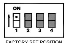
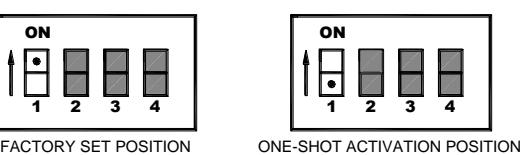
The dot shown above marks the position of the switch.
Note: When using the one-shot activation option, the following point must be observed: With the activation switch contacts in the maintained closed position, and after completion of a full open/close cycle, before the next activation can occur, the
activation switch contacts must be held open for 4 seconds (for resetting the delay circuit) before closing to reactivate the cycle.
Electrified Door Hardware
The 1420 is provided with an output for wiring to fail safe type door hardware (marked as FSF at terminal block TB1) and another output for fail secure type door hardware (marked as FSC). All electrified door hardware must be rated 24VDC. The maximum allowable current draw for either output is 2 amps. (If a pair of doors is used in the application, and each leaf contains electrified door hardware, the maximum current draw for each device is 1.0 amp.)
The most common type of fail safe door hardware used with this kind of system application is the electromagnetic lock. A complete riser diagram and point-to-point wiring diagram depicting an application utilizing this type of electrified door hardware can be found at the end of this manual, shown in Figures 1a and 1b respectively. Although not as common as an electromagnetic lock, a fail safe electric door strike can also be applied to an automated door opening system using the FSF output. When using an electromagnetic lock for locking and releasing the door, there cannot be a mechanical latching device, such as a mortise or cylindrical lockset, installed in the door. This would prevent automatic opening of the door. The opening must be equipped with push-pull hardware trim only.
The most common type of fail secure door hardware used is the electric door strike. A complete riser diagram and point-to-point wiring diagram depicting an application utilizing this type of electrified door hardware can be found at the end of this manual, shown in Figures 2a and 2b respectively.
A latching type of fail secure door hardware, such as the ACSI Series 1550K-MD kit with motor drive or the Series 1550-MD factory modified version, can be used providing that it is designed to have its latch retracted in less than 1.5 seconds upon application of power when the cycle has been activated, and providing the solenoid or motor used in the device does not draw more than 1 amp at 24VDC. For applications using the Series 1550K-MD or 1550-MD, a complete set of riser diagrams and point-to-point wiring diagrams can be found on the Architectural Control Systems website at www.acsi-inc.com.
For special applications, both fail safe and fail secure door hardware can be used on the same door, if required. As an example, a single door may contain a fail safe electromagnetic lock on the door frame header and a rim exit device with fail secure electric latch retraction on the door. When the system is activated, power is removed from the electromagnetic lock at the same time power is applied to the rim exit device (for retracting its latch) prior to signaling the automatic door operator to open. Each device can separately draw up to 1 amp of current (or up to 2 amps for pair door applications using electrified door hardware on each leaf) since both the fail safe and fail secure devices, at no time, are drawing current simultaneously.
CAUTION! Do not use the ACSI Series 1550C, Von Duprin Series EL, or any other manufacturer of high inrush electric latch retraction exit devices with the 1420 power supply. These devices can generate an initial high current pulse in excess of 6 amps. The 1420 is not designed to handle that amount of current draw. Special power supplies, specifically designed for use with these type of
exit devices, are required by the manufacturer to comply with UL safety requirements. Before using an exit device modified for electric latch retraction with the 1420, make sure to check out its electrical specifications, for ratings that comply with those of the 1420 power supply, and ensure that the manufacturer of the device does not require it to be used with a special power supply offered by that manufacturer.
Automatic Door Operator
The output terminals marked ADO at terminal block TB1 provide the electrical signal to the input of the automatic door operator for activating its "door open" cycle. This electrical signal is in the form of dry contacts from a relay located on the same p.c. board as TB1. The ADO output can be programmed for either a normally open or a normally closed contact signal. Most automatic door operator units accept a normally open contact signal, and the onboard dip switch bank is factory set for a "N.O." output. But in the event that a normally closed (N.C.) signal should ever be required for activating an automatic door operator directly or indirectly, reconfigure the dip switch bank #2 and #3 switches per the illustration shown below:
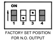
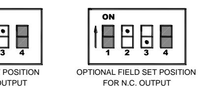
The dot shown above marks the position of the switch.
Emergency Release Switch
The emergency release switch input, marked as ERS at terminal block TB1, accepts a normally closed switch (or normally closed relay contacts) that is associated with some form of emergency, such as a panic alarm, or fire alarm. When the switch contacts open during an emergency situation, the electrified door hardware, regardless if it is fail safe or fail secure function, will unlock the door for immediate access. The 1420 comes from the factory with the emergency release switch input disabled. To enable the ERS input, switch #4 from the onboard dip switch bank must be placed opposite the "ON" position, as shown below:
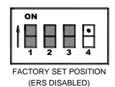
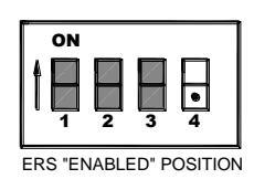
The dot shown above marks the position of the switch.
Auxiliary 24VDC Output
This output, marked as 24V at terminal block TB1, provides a constant 24 volts that can be used to power keypads, motion detectors, LEDs, incandescent status indicators, etc. A maximum load of 1 amp is allowed across this output.
Note: The maximum output current for the 1420 power supply is 2 amps with all outputs combined. If the electrified door hardware draws a maximum of 1 amp, the auxiliary output can draw up to 1 amp. If the total current draw exceeds 1 amp for all electrified door hardware used, then the auxiliary output can only draw the amount of current that is equal to the difference between the total current drawn by the electrified door hardware and the 2 amp maximum.
Trouble Shooting Tips
Listed below are some problems that might be encountered during installation, or at any other time, and possible solutions for correcting them.
! CAUTION !
THIS UNIT CONTAINS AREAS OF EXPOSED HIGH VOLTAGE. ALL TROUBLE SHOOTING AND MAINTENANCE SHOULD BE PERFORMED BY A QUALIFIED ELECTRICIAN.
-
No output voltage measured across terminals 24V, FSF, or FSC.
- o Check for 120VAC across terminals of input to power supply module.
- o If 120VAC is present, disconnect field wires from all used outputs (Auxiliary 24V, FSF, FSC) and measure for 24VDC across the "24V" terminals.
- o If 24VDC is now present, check for shorts across field wires for each output . If the load is electrified door hardware installed in the door, check the electric hinge for pinched wires behind each leaf. Also check for shorted wires between the electrified door hardware and raceway in the door if the raceway is metal conduit.
- o If 24VDC is not present across terminals marked "24V" (with field wires still disconnected from all outputs), disconnect the red and black wire leads connected to the +,- terminals of the output to the power supply module and check for 24VDC at this output. If voltage is now present across the power supply module's output, it can be assumed that there is a short circuit somewhere on the control board and it will need to be replaced. If voltage is still not present across the output to the power supply module, then it can be assumed the power supply module itself is damaged and must be replaced.
-
The electrified door hardware behaves the opposite of what was expected, i.e., it locks when intended to unlock, or unlocks when intended to lock.
- o A fail safe type door hardware may be incorrectly wired to the fail secure output terminals (FSC). It must be wired to the terminals marked "FSF".
- o A fail secure type door hardware may be incorrectly wired to the fail safe output terminals (FSF). It must be wired to the terminals marked "FSC".
- o Make sure that the electrified door hardware has been correctly modified for the function intended: Fail Safe (power to lock), Fail Secure (power to unlock).
-
A maintained activation switch is intended to be used to initiate the automated door opening system and hold the door in an open position; but when activated, the door goes through a complete open/close cycle instead of staying open.
- o Dip switch #1 from the onboard dip switch bank is set for "One-Shot Activation". Correct this by placing dip switch #1 to the "ON" position. (See the above section entitled, "one-Shot Activation Option" under "Activation Switches" for more details.)
-
When the 1420 is powered up and the green "Power" indicator on the small p.c. board is lit, the electrified door hardware immediately releases, followed by activation of the automatic door operator, without manually activating the system.
- o Field wires from the activation switch may be shorted together.
- o The 1420 activation inputs have been mistakenly wired to the normally closed contacts of the activation switch instead of the normally open contacts.
-
When the 1420 is powered up and the green "Power" indicator on the small p.c. board is lit, the electrified door hardware does not release, but the automatic door operator is activated and attempting to open the door, without manually activating the system.
- o The dip switch settings for the ADO output are not correct, or are reversed from what they should be. Determine if the automatic door operator activation input accepts a contact closure or open contact signal for opening the door; then set the dip switches accordingly as per instructed in the section above entitled, "Automatic Door Operator".
-
The electrified door hardware all of a sudden releases, and the automatic door operator opens the door without being manually activated (characteristic of a symptom involving fail safe door hardware).
- o The power supply has shut down due to a shorted output.
- o Loss of AC power to the 1420.
-
The automatic door operator all of a sudden becomes activated and is attempting to open the door; but the electrified door hardware remains locked, preventing the door from opening (characteristic of a symptom involving fail secure door hardware).
- o The power supply has shut down due to a shorted output.
- o Loss of AC power to the 1420.
For trouble shooting assistance, contact ACSI Technical Support: 1-800-753-5558
SPECIFICATIONS:
Input Voltage: 120VAC/240VAC, 50/60Hz
AC Current: 900mA/120VAC, 600mA/240VAC
Output Voltage: 24VDC Filtered, Regulated
Output Current: 2.0A Output Power: 48W
Protection: Overload, Over Voltage, Short Circuit

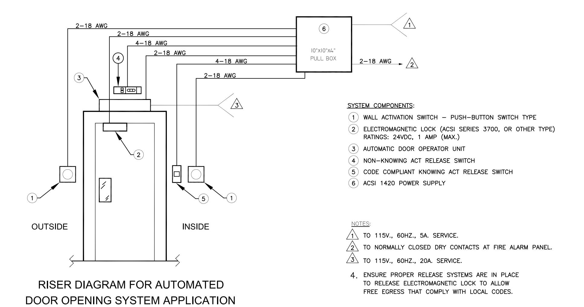
FIG. 1a
USING AN ELECTROMAGNETIC LOCK
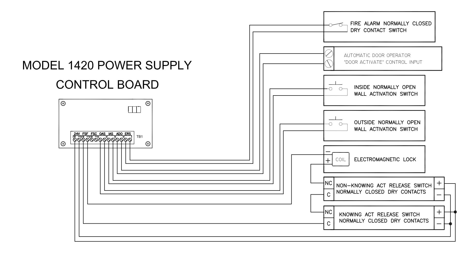
POINT-TO-POINT WIRE DIAGRAM FOR AUTOMATED DOOR OPENING SYSTEM APPLICATION USING AN ELECTROMAGNETIC LOCK
FIG. 1b
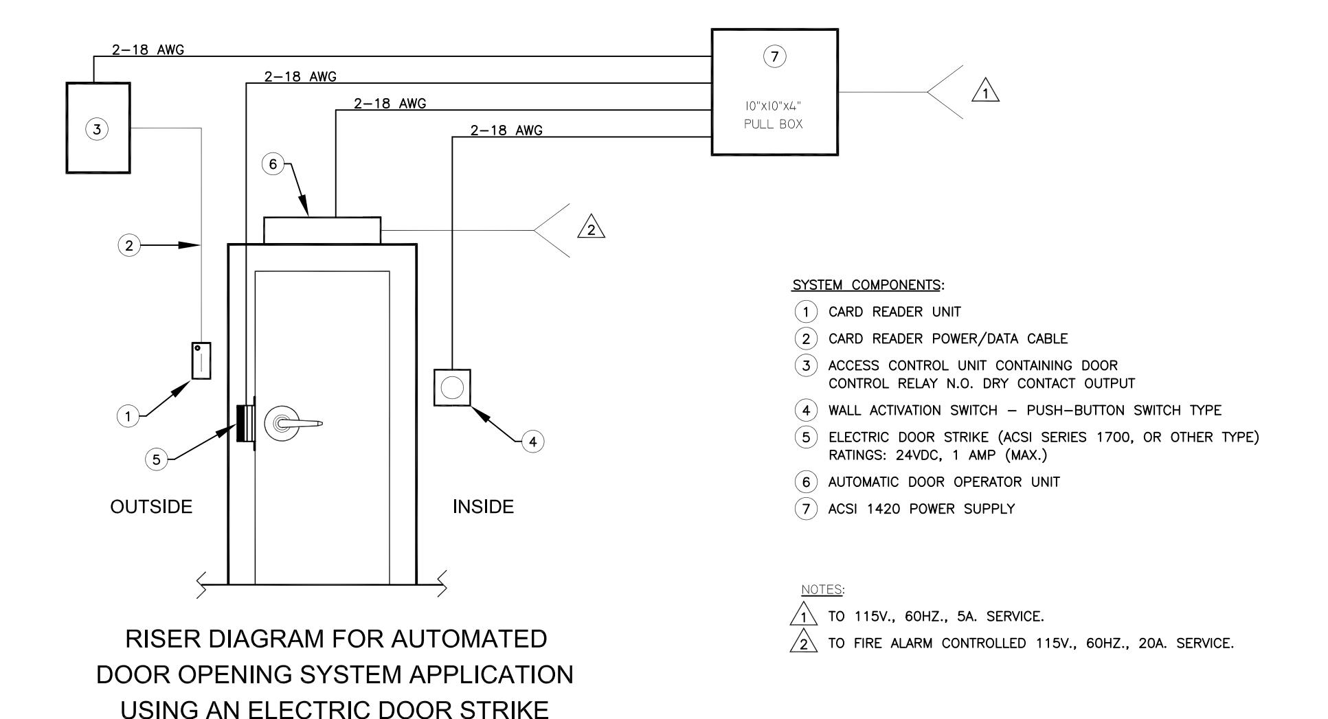
FIG. 2a
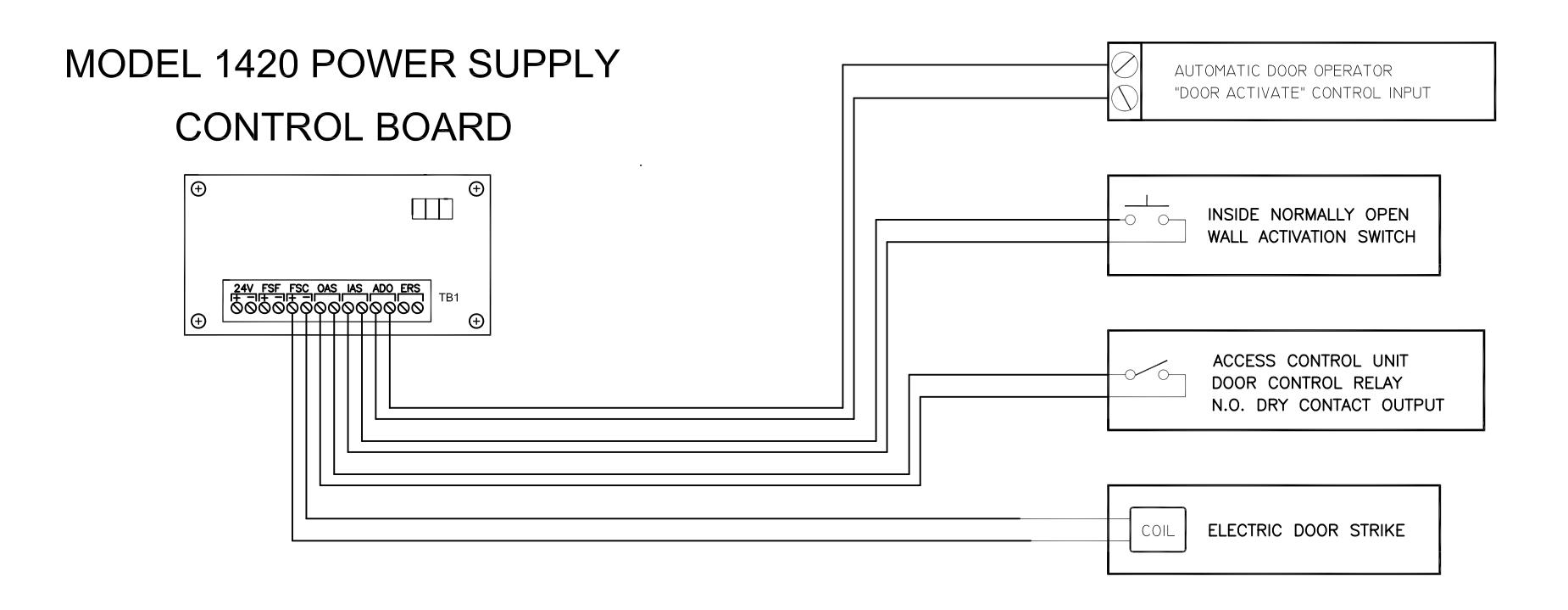
POINT-TO-POINT WIRE DIAGRAM FOR AUTOMATED DOOR OPENING SYSTEM APPLICATION USING AN ELECTRIC DOOR STRIKE
FIG. 2b
MODEL 1420 POWER SUPPLY
SPECIFICATIONS:
INPUT VOLTAGE: 120VAC/240VAC, 50/60Hz AC CURRENT: 900mA/120VAC, 600mA/240VAC
OUTPUT VOLTAGE: 24VDC FILTERED, REGULATED OUTPUT CURRENT: 2.0A OUTPUT POWER: 48W
PROTECTION: OVERLOAD, OVER VOLTAGE, SHORT CIRCUIT
ACCESS CONTROL POWER SUPPLY CLASS 2 OUTPUTS
SECURITY

EQUIPMENT 4M73
RED LED
INDICATOR
POWER
MFG DATE:
RED
BLACK
⊗+
⊗+
Ŋι
⊗ı
POWER SUPPLY INTENDED FOR INDOOR USE ONLY
STRIP WIRE BACK 6mm. WIRES MUST BE FULLY INSERTED INTO TERMINALS SO THAT NO BARE METAL IS EXPOSED. FLEXIBLE CABLE: ALL STRANDS MUST BE SECURED IN TERMINAL. USE COPPER CONDUCTORS ONLY.
TERMINAL SIZE RANGE: AWG24-10 FOR A TYPE AWG24-14 FOR B TYPE
120VAC OR 240VAC INPUT
CLASS 2 DOUBLE INSULATION. NO EARTH GROUND WIRE REQUIRED.
000 CONTROL BOARD 24V POWER CONNECTOR J1
BLACK
RED
USE INSTALLATION
INSTRUCTIONS
II - 1400-5
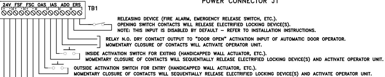
RELEASING DEVICE (FIRE ALARM, EMERGENCY RELEASE SWITCH, ETC.). OPENING SWITCH CONTACTS WILL RELEASE ELECTRIFIED LOCKING DEVICE(S). NOTE: THIS INPUT IS DISABLED BY DEFAULT - REFER TO INSTALLATION INSTRUCTIONS.
RELAY N.O. DRY CONTACT OUTPUT TO "DOOR OPEN" ACTIVATION INPUT OF AUTOMATIC DOOR OPERATOR. MOMENTARY CLOSURE OF CONTACTS WILL ACTIVATE OPERATOR UNIT.
OUTSIDE ACTIVATION SWITCH FOR ENTRY (HANDICAPPED WALL ACTUATOR, ETC.). MOMENTARY CLOSURE OF CONTACTS WILL SEQUENTIALLY RELEASE ELECTRIFIED LOCKING DEVICE(S) AND ACTIVATE OPERATOR UNIT.
TO FAIL SECURE ELECTRIFIED LOCKING DEVICE. BOTH TYPE DEVICES CAN BE CONNECTED AND OPERATED SIMULTANEOUSLY TO FAIL SAFE ELECTRIFIED LOCKING DEVICE.
z(x)
UNSWITCHED AUXILIARY 24VDC OUTPUT.
NOTE: THE SUM OF ALL OUTPUTS CANNOT EXCEED 2 AMPS.


ACSI Series 1550K-MD and 1550-MD Motor Drive Electric Latch Retraction
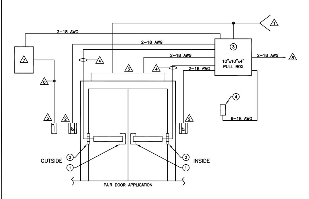
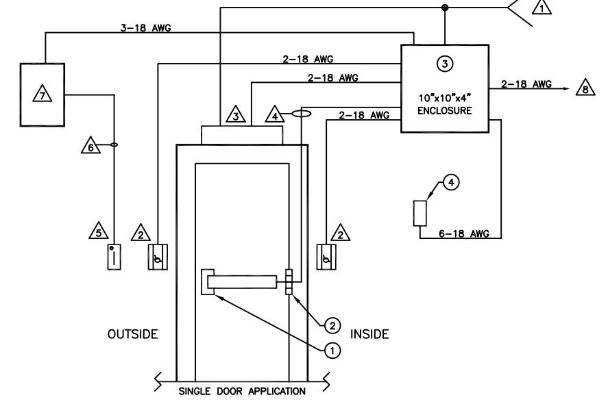
Riser and Point-to-Point Drawings for Standard Access Control and Day/Night Applications for Openings Using Automatic Door Operators
For Use with ACSI Part Numbers 1420 and 1420-DN
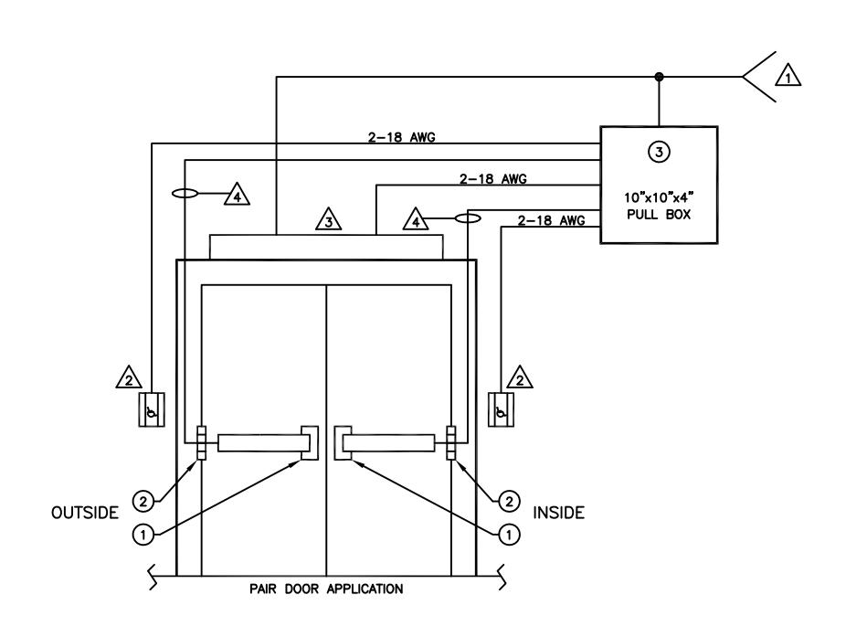
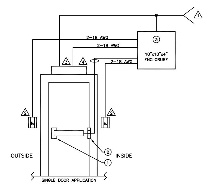
ACSI SUPPLIED EQUIPMENT:
- SERIES 1550K-MD OR 1550-MD MOTOR DRIVE ELECTRIC LATCH RETRACTION
- 2 SERIES 1100 POWER TRANSFER HINGE
- (3) 1420 POWER SUPPLY
NOTES:
1 TO 115V., 60HZ., 15A. SERVICE.
NOTE: IF FIRE ALARM INTERFACE IS REQUIRED, RUN 115V SERVICE THROUGH FIRE ALARM—CONTROLLED RELAY N.C. CONTACTS.
2 wall activation switch
AUTOMATIC DOOR OPERATOR
| WIRE GAUGE | MAX. LENGTH 2—COND. CABLE | 22 AWG | 70 FEET | 20 AWG | 110 FEET | 18 AWG | 180 FEET |
16 AWG 280 FEET 14 AWG 450 FEET 12 AWG 720 FEET
RISER DIAGRAM FOR STANDARD AUTOMATED DOOR OPENING SYSTEM APPLICATION USING SERIES 1550K-MD OR 1550-MD MOTOR DRIVE ELR DEVICES
| ARCHITECTURAL CONTROL SYSTEMS, INCORPORATED ST. LOUIS, MISSOURI 1-800-753-5558 | S NOTED +.007 DRILL001 +.001 REAM000 PUNCH001 |
10/7/14
DATE |
RELEASED
REV. |
CRH
APPRV. |
|
|---|---|---|---|---|---|
| DESCRIPTION | DRAWING NO. | MATERIAL | SCALE AV | DRAWN BY CRH | DATE 10/7/14 |
| ACSI P/N 1420 | REF 6037-R1 | SHEET 1 OF 1 | APPRV. BY CRH | DATE 10/7/14 | |
| ELR ACCESS CONTROL | | KEF 6037-K1 | DO NOT | SCALE THIS I | RAWING | |
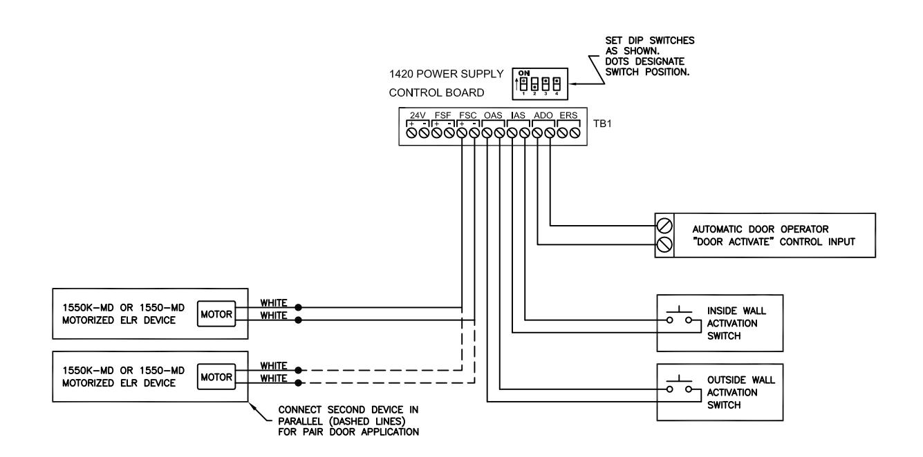
OUTSIDE OR INSIDE WALL ACTIVATION SWITCH SEQUENTIALLY RETRACTS LATCHBOLT AND ACTIVATES AUTOMATIC DOOR OPERATOR.
IF THE 1420 POWER SUPPLY IS WIRED TO A FIRE ALARM CONTROL PANEL, AN ALARM CONDITION WILL IMMEDIATELY PROJECT LATCHBOLT AND DISABLE USE OF OUTSIDE AND INSIDE WALL ACTIVATION SWITCHES.
NOTE: IF THE FIRE ALARM ACTIVATES DURING A "DOOR OPEN" CYCLE, THE LATCHBOLT WILL IMMEDIATELY PROJECT AND THE OUTSIDE/INSIDE WALL ACTIVATION SWITCHES WILL IMMEDIATELY BECOME DISABLED, BUT THE THE SIGNAL TO THE AUTOMATIC DOOR OPERATOR TRIGGER INPUT WILL TERMINATE APPROXIMATELY ½ SEC. AFTER THE ALARM HAS ACTIVATED.
POINT-TO-POINT WIRING DIAGRAM STANDARD ACCESS CONTROL WITH AUTOMATIC DOOR OPERATOR USING SERIES 1550K-MD OR 1550-MD MOTOR DRIVE ELR DEVICES
| ARCHITECTURAL CONTROL SYST INCORPORATED ST. LOUIS, MISSOU | EMS, | TOLERANCES UNLESS FRACTION ±1/64 DECIMAL ± .006 |
S NOTED +.007
DRILL001 +.001 REAM000 +.004 |
10/7/14 | RELEASED | CRH |
|---|---|---|---|---|---|---|
| 1-800-753-5558 | ANGULAR ±1° | PUNCH001 | DATE | REV. | APPRV. | |
| DESCRIPTION | DRAWING NO. | MATERIAL | SCALE AV | DRAWN BY CRH | DATE 10/7/14 | |
| ACSI P/N 1420 | DEE | 6037-P1 | SHEET 1 OF 1 | APPRV. BY CRH | DATE 10/7/14 | |
| ELR ACCESS CONTROL | KEF | 0037-21 | DO NOT | SCALE THIS D | RAWING |
ACSI SUPPLIED EQUIPMENT:
- 1 SERIES 1550K-MD OR 1550-MD MOTOR DRIVE ELECTRIC LATCH RETRACTION
- 2 SERIES 1100 POWER TRANSFER HINGE
- (3) 1420 POWER SUPPLY
- RM RELAY MODULE
NOTE: DO NOT LOCATE MORE THAN 10 FT. FROM POWER SUPPLY
1 TO 115V., 60HZ., 15A. SERVICE.
NOTE: IF FIRE ALARM INTERFACE IS REQUIRED, RUN 115V SERVICE THROUGH FIRE ALARM-CONTROLLED RELAY N.C. CONTACTS.
wall activation switch automatic door operator
| A | WIRE | GAUGE | MAX. | LENGTH | 2-COND. | CABLE |
|---|---|---|---|---|---|---|
| _ | 22 | AWG | 70 | FEET | ||
| 20 | AWG | 110 | FEET | |||
| 18 | AWG | 180 | FEET |
16 AWG 280 FEET 14 AWG 450 FEET 720 FEET 12 AWG
5 CARD READER UNIT
CARD READER POWER/DATA CABLE
CARD ACCESS CONTROL UNIT CONTAINING DOOR CONTROL RELAY RESPONDING TO CARD READER SWIPE FOR MOMENTARY AUTHORIZED ENTRY (NIGHT MODE)
ACCESS CONTROL SYSTEM DAY/NIGHT SWITCHING OUTPUT (TIME CLOCK, COMPUTER-CONTROLLED TIME SCHEDULE, ETC.)
RISER DIAGRAM FOR DAY/NIGHT AUTOMATED DOOR OPENING SYSTEM APPLICATION USING SERIES 1550K-MD OR 1550-MD MOTOR DRIVE ELR DEVICES
|
ARCHITECTURAL
CONTROL SYST INCORPORATED ST. LOUIS, MISSOU 1-800-753-8588 |
EMS, FRACTION ±1/64 | *** NOTED +.007 DRILL +.007 +.001 ********************************** |
2/10/15
10/7/14 DATE |
A
RELEASED REV. |
CRH
CRH APPRV. |
|---|---|---|---|---|---|
| DESCRIPTION | DRAWING NO. | MATERIAL | SCALE AU | DRAWN BY CRH | DATE 10/7/14 |
| ACSI P/N 1420-DN | REF 6037-R2 | SHEET 1 OF 1 | APPRV. BY CRH | DATE 10/7/14 | |
| ELR ACCESS CONTROL | REF 0037-R2 | DO NOT | SCALE THIS D | RAWING |
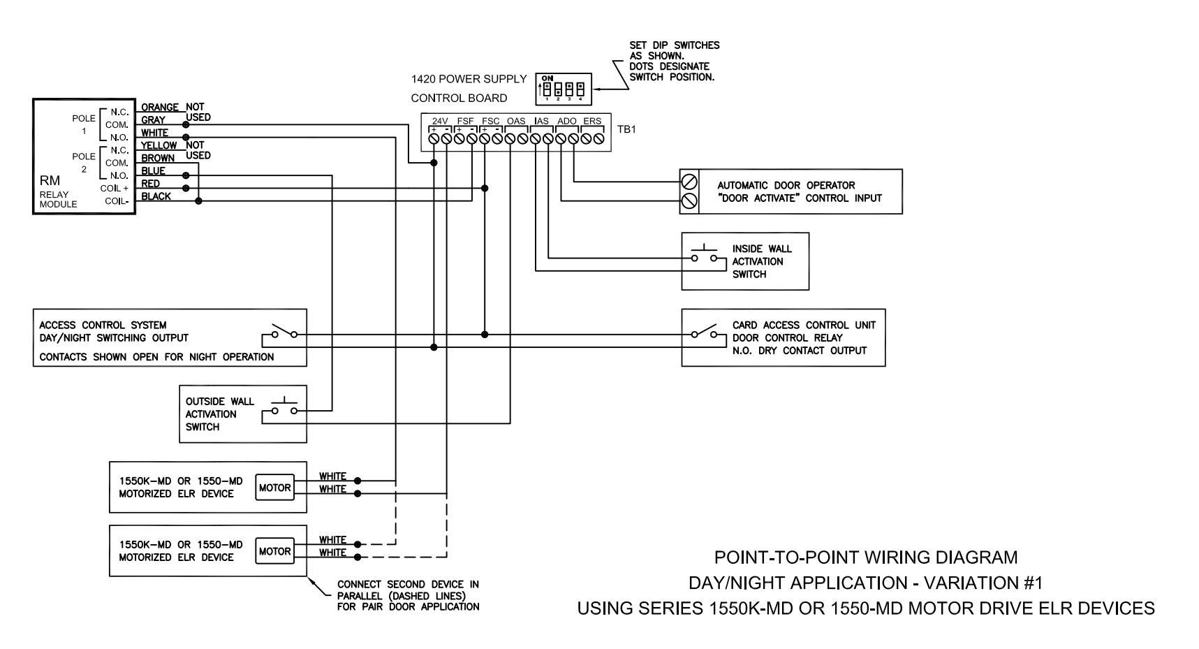
WHEN THE ACCESS CONTROL SYSTEM DAY/NIGHT SWITCHING OUTPUT IS SET FOR DAY OPERATION (DRY CONTACTS CLOSED), THE LATCHBOLT WILL RETRACT. PUSHING THE OUTSIDE OR INSIDE WALL ACTIVATION SWITCH WILL ACTIVATE THE AUTOMATIC DOOR OPERATOR.
WHEN THE ACCESS CONTROL SYSTEM DAY/NIGHT SWITCHING OUTPUT IS SET FOR NIGHT OPERATION (DRY CONTACTS OPEN), THE LATCHBOLT WILL PROJECT AND THE OUTSIDE WALL ACTIVATION SWITCH BECOMES DISABLED. A VALID SWIPE FROM THE CARD READER WILL TEMPORARILY RETRACT THE LATCHBOLT. WHILE THE CARD READER IS IN ITS ACTIVATED STATE, THE OUTSIDE WALL ACTIVATION SWITCH IS ENABLED FOR ACTIVATING THE AUTOMATIC DOOR OPERATOR. THE INSIDE WALL ACTIVATION SWITCH IS ALWAYS ENABLED IN NIGHT MODE AND WILL SEQUENTIALLY RETRACT THE LATCHBOLT AND ACTIVATE THE AUTOMATIC DOOR OPERATOR.
IF THE 1420 POWER SUPPLY IS WIRED TO A FIRE ALARM CONTROL PANEL, AN ALARM CONDITION OCCURRING WHILE IN DAY MODE WILL IMMEDIATELY PROJECT THE LATCHBOLT AND DISABLE USE OF THE OUTSIDE AND INSIDE WALL ACTIVATION SWITCHES. IN NIGHT MODE WHEN A FIRE ALARM CONDITION OCCURS, THE LATCHBOLT WILL REMAIN PROJECTED AND BOTH OUTSDIE AND INSIDE WALL ACTIVATION SWITCHES BECOME DISABLED.
NOTE: IF THE FIRE ALARM ACTIVATES DURING A "DOOR OPEN" CYCLE (DAY OR NIGHT MODE), THE LATCHBOLT WILL IMMEDIATELY PROJECT AND THE OUTSIDE/INSIDE WALL ACTIVATION SWITCHES WILL IMMEDIATELY BECOME DISABLED, BUT THE THE SIGNAL TO THE AUTOMATIC DOOR OPERATOR TRIGGER INPUT WILL TERMINATE APPROXIMATELY & SEC. AFTER THE ALARM HAS ACTIVATED.
|
ARCHITECTURAL
CONTROL SYSTI INCORPORATED ST. LOUIS, MISSOUI 1-800-783-5588 |
EMS, FRACTION ±1/64 | ************************************** |
12/18/14
10/7/14 DATE |
A
RELEASED REV. |
CRH
CRH APPRV. |
|---|---|---|---|---|---|
| DESCRIPTION | DRAWING NO. | MATERIAL | SCALE AV | DRAWN BY CRH | DATE 10/7/14 |
| ACSI P/N 1420-DN | REF 6037-P2-1 | SHEET 1 OF 1 | APPRV. BY CRH | DATE 10/7/14 | |
| ELR ACCESS CONTROL | KEF 6037-F2-1 | DO NOT | SCALE THIS D | RAWING |
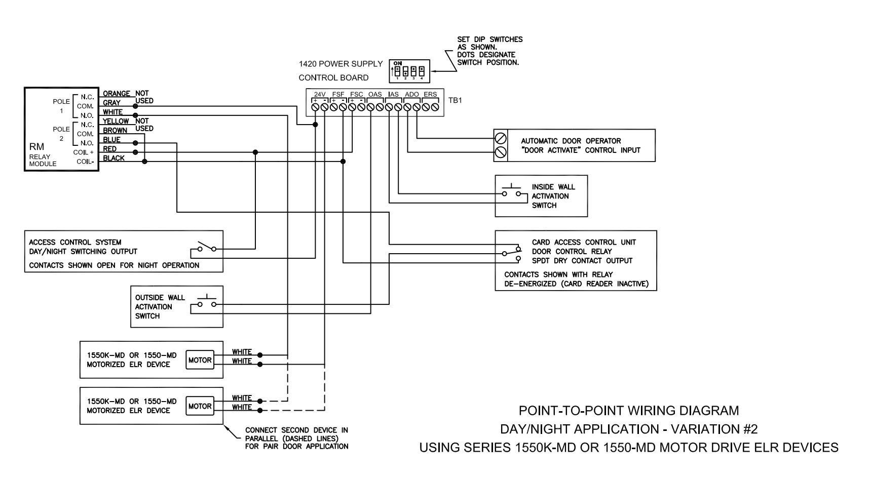
WHEN THE ACCESS CONTROL SYSTEM DAY/NIGHT SWITCHING OUTPUT IS SET FOR DAY OPERATION (DRY CONTACTS CLOSED), THE LATCHBOLT WILL RETRACT. PUSHING THE OUTSIDE OR INSIDE WALL ACTIVATION SWITCH WILL ACTIVATE THE AUTOMATIC DOOR OPERATOR.
WHEN THE ACCESS CONTROL SYSTEM DAY/NIGHT SWITCHING OUTPUT IS SET FOR NIGHT OPERATION (DRY CONTACTS OPEN), THE LATCHBOLT WILL PROJECT AND THE OUTSIDE WALL ACTIVATION SWITCH BECOMES DISABLED. A VALID SWIPE FROM THE CARD READER WILL ENABLE THE OUTSIDE WALL ACTIVATION SWITCH TO SEQUENTIALLY RETRACT THE LATCHBOLT AND ACTIVATE THE AUTOMATIC DOOR OPERATOR. THE INSIDE WALL ACTIVATION SWITCH IS ALWAYS ENABLED IN NIGHT MODE AND WILL SEQUENTIALLY RETRACT THE LATCHBOLT AND ACTIVATE THE AUTOMATIC DOOR OPERATOR.
IF THE 1420 POWER SUPPLY IS WIRED TO A FIRE ALARM CONTROL PANEL, AN ALARM CONDITION OCCURRING WHILE IN DAY MODE WILL IMMEDIATELY PROJECT THE LATCHBOLT AND DISABLE USE OF THE OUTSIDE AND INSIDE WALL ACTIVATION SWITCHES. IN NIGHT MODE WHEN A FIRE ALARM CONDITION OCCURS, THE LATCHBOLT WILL REMAIN PROJECTED AND BOTH OUTSIDE AND INSIDE WALL ACTIVATION SWITCHES BECOME DISABLED.
NOTE: IF THE FIRE ALARM ACTIVATES DURING A "DOOR OPEN" CYCLE (DAY OR NIGHT MODE), THE LATCHBOLT WILL IMMEDIATELY PROJECT AND THE OUTSIDE/INSIDE WALL ACTIVATION SWITCHES WILL IMMEDIATELY BECOME DISABLED, BUT THE THE SIGNAL TO THE AUTOMATIC DOOR OPERATOR TRIGGER INPUT WILL TERMINATE APPROXIMATELY & SEC. AFTER THE ALARM HAS ACTIVATED.
|
ARCHITECTURAL
CONTROL SYST INCORPORATED ST. LOUIS, MISSOU 1-800-783-5858 |
EMS, FRACTION ±1/64 | ************************************** |
12/18/14
10/8/14 DATE |
A
RELEASED REV. |
CRH
CRH APPRV. |
|---|---|---|---|---|---|
| DESCRIPTION | DRAWING NO. | MATERIAL | SCALE AV | DRAWN BY CRH | DATE 10/8/14 |
| ACSI P/N 1420-DN | REF 6037-P2-2 | SHEET 1 OF 1 | APPRV. BY CRH | DATE 10/8/14 | |
| ELR ACCESS CONTROL | REF 6037-F2-2 | DO NOT | SCALE THIS D | RAWING |
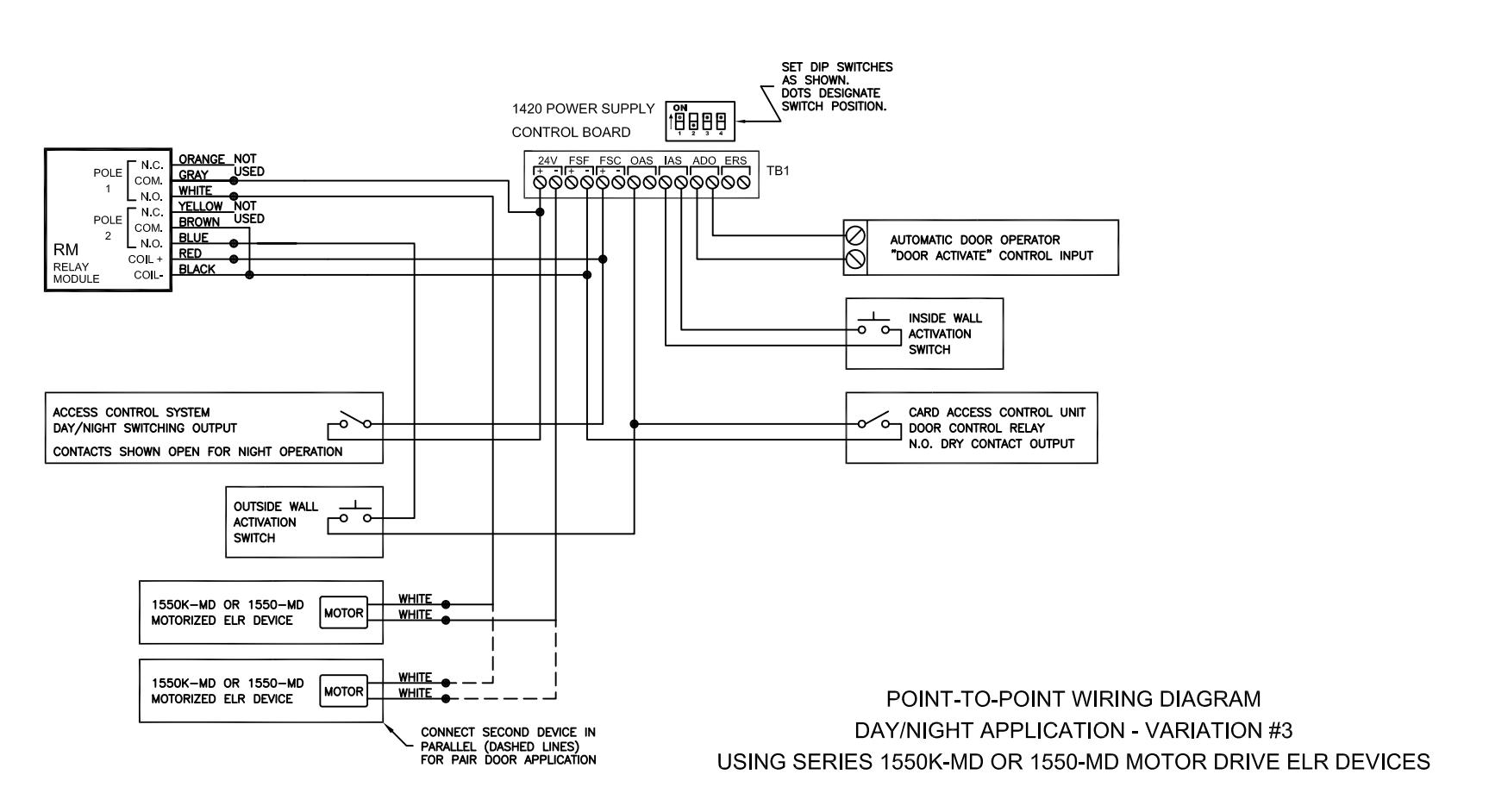
WHEN THE ACCESS CONTROL SYSTEM DAY/NIGHT SWITCHING OUTPUT IS SET FOR DAY OPERATION (DRY CONTACTS CLOSED), THE LATCHBOLT WILL RETRACT. PUSHING THE OUTSIDE OR INSIDE WALL ACTIVATION SWITCH WILL ACTIVATE THE AUTOMATIC DOOR OPERATOR.
WHEN THE ACCESS CONTROL SYSTEM DAY/NIGHT SWITCHING OUTPUT IS SET FOR NIGHT OPERATION (DRY CONTACTS OPEN), THE LATCHBOLT WILL PROJECT AND THE OUTSIDE WALL ACTIVATION SWITCH BECOMES DISABLED. A VALID SWIPE FROM THE CARD READER WILL SEQUENTIALLY RETRACT THE LATCHBOLT AND ACTIVATE THE AUTOMATIC DOOR OPERATOR. THE INSIDE WALL ACTIVATION SWITCH IS ALWAYS ENABLED IN NIGHT MODE AND WILL SEQUENTIALLY RETRACT THE LATCHBOLT AND ACTIVATE THE AUTOMATIC DOOR OPERATOR.
IF THE 1420 POWER SUPPLY IS WIRED TO A FIRE ALARM CONTROL PANEL, AN ALARM CONDITION OCCURRING WHILE IN DAY MODE WILL IMMEDIATELY PROJECT THE LATCHBOLT AND DISABLE USE OF THE OUTSIDE AND INSIDE WALL ACTIVATION SWITCHES. IN NIGHT MODE WHEN A FIRE ALARM CONDITION OCCURS, THE LATCHBOLT WILL REMAIN PROJECTED AND BOTH OUTSDIE AND INSIDE WALL ACTIVATION SWITCHES BECOME DISABLED.
NOTE: IF THE FIRE ALARM ACTIVATES DURING A "DOOR OPEN" CYCLE (DAY OR NIGHT MODE), THE LATCHBOLT WILL IMMEDIATELY PROJECT AND THE OUTSIDE/INSIDE WALL ACTIVATION SWITCHES WILL IMMEDIATELY BECOME DISABLED, BUT THE THE SIGNAL TO THE AUTOMATIC DOOR OPERATOR TRIGGER INPUT WILL TERMINATE APPROXIMATELY ½ SEC. AFTER THE ALARM HAS ACTIVATED.
| ARCHITECTURAL CONTROL SYSTEMS, INCORPORATED ST. LOUIS, MISSOURI 1-800-733-8558 AMOURA 24 | S MOTED |
12/18/14
10/8/14 DATE |
A
RELEASED REV. |
CRH
CRH APPRV. |
|
|---|---|---|---|---|---|
| DESCRIPTION | DRAWING NO. | MATERIAL | SCALE AU | DRAWN BY CRH | DATE 10/8/14 |
| ACSI P/N 1420-DN | REF 6037-P2-3 | SHEET 1 OF 1 | APPRV. BY CRH | DATE 10/8/14 | |
| ELR ACCESS CONTROL | | KEF 6037-F2-3 | DO NOT | SCALE THIS D | RAWING | |
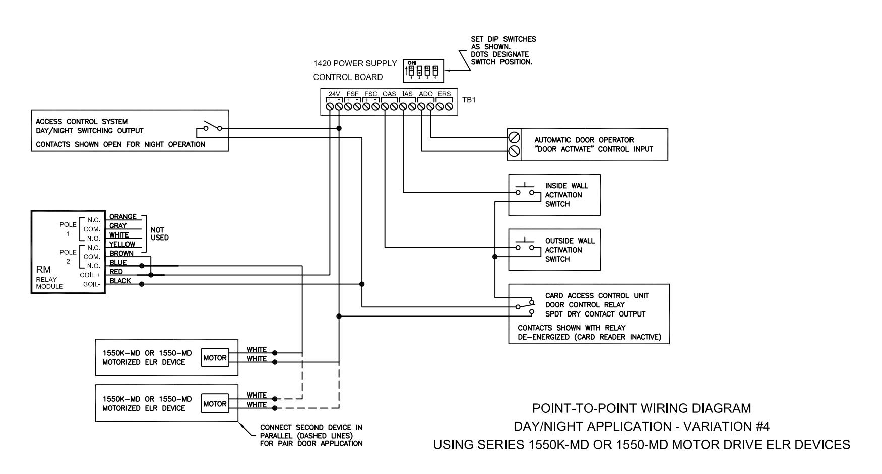
WHEN THE ACCESS CONTROL SYSTEM DAY/NIGHT SWITCHING OUTPUT IS SET FOR DAY OPERATION (DRY CONTACTS CLOSED), THE LATCHBOLT WILL RETRACT. PUSHING THE OUTSIDE OR INSIDE WALL ACTIVATION SWITCH WILL ACTIVATE THE AUTOMATIC DOOR OPERATOR.
WHEN THE ACCESS CONTROL SYSTEM DAY/NIGHT SWITCHING OUTPUT IS SET FOR NIGHT OPERATION (DRY CONTACTS OPEN), THE LATCHBOLT WILL PROJECT AND BOTH THE OUTSIDE AND INSIDE WALL ACTIVATION SWITCHES BECOME DISABLED. A VALID SWIPE FROM THE CARD READER WILL ONLY RETRACT THE LATCHBOLT. THE DOOR MUST BE PULLED OPEN MANUALLY FOR ENTRY OR PUSHED OPEN MANUALLY FOR EXITING.
IF THE 1420 POWER SUPPLY IS WIRED TO A FIRE ALARM CONTROL PANEL, AN ALARM CONDITION OCCURRING WHILE IN DAY MODE WILL IMMEDIATELY PROJECT THE LATCHBOLT AND DISABLE USE OF THE OUTSIDE AND INSIDE WALL ACTIVATION SWITCHES. IN NIGHT MODE WHEN A FIRE ALARM CONDITION OCCURS, THE LATCHBOLT WILL REMAIN PROJECTED. BY DEFAULT, BOTH OUTSIDE AND INSIDE WALL ACTIVATION SWITCHES ARE DISABLED IN NIGHT MODE.
NOTE: IF THE FIRE ALARM ACTIVATES DURING A "DOOR OPEN" CYCLE (DAY MODE ONLY), THE LATCHBOLT WILL IMMEDIATELY PROJECT AND THE OUTSIDE/NISIDE WALL ACTIVATION SWITCHES WILL IMMEDIATELY BECOME DISABLED, BUT THE SIGNAL TO THE AUTOMATIC DOOR OPERATOR TRIGGER INPUT WILL TERMINATE APPROXIMATELY X SEC. AFTER THE ALARM HAS ACTIVATED.
|
ARCHITECTURAL
CONTROL SYST INCORPORATED ST. LOUIS, MISSOU 1-800-753-5558 |
EMS, FRACTION ±1/64 |
+.007
DRILL001 +.001 +.001 REAM000 PUNCH001 |
12/18/14
10/8/14 DATE |
A
RELEASED REV. |
CRH
CRH APPRV. |
|---|---|---|---|---|---|
| DESCRIPTION | DRAWING NO. | MATERIAL | SCALE AV | DRAWN BY CRH | DATE 10/8/14 |
| ACSI P/N 1420-DN | REF 6037-P2-4 | SHEET 1 OF 1 | APPRV. BY CRH | DATE 10/8/14 | |
| ELR ACCESS CONTROL | | REF 6037-P2-4 | DO NOT | SCALE THIS D | RAWING |