5100 Series Standard Slide Track Arm Installation Instructions 5100-i-cl00577-rev7
Open the original PDF document
View PDF

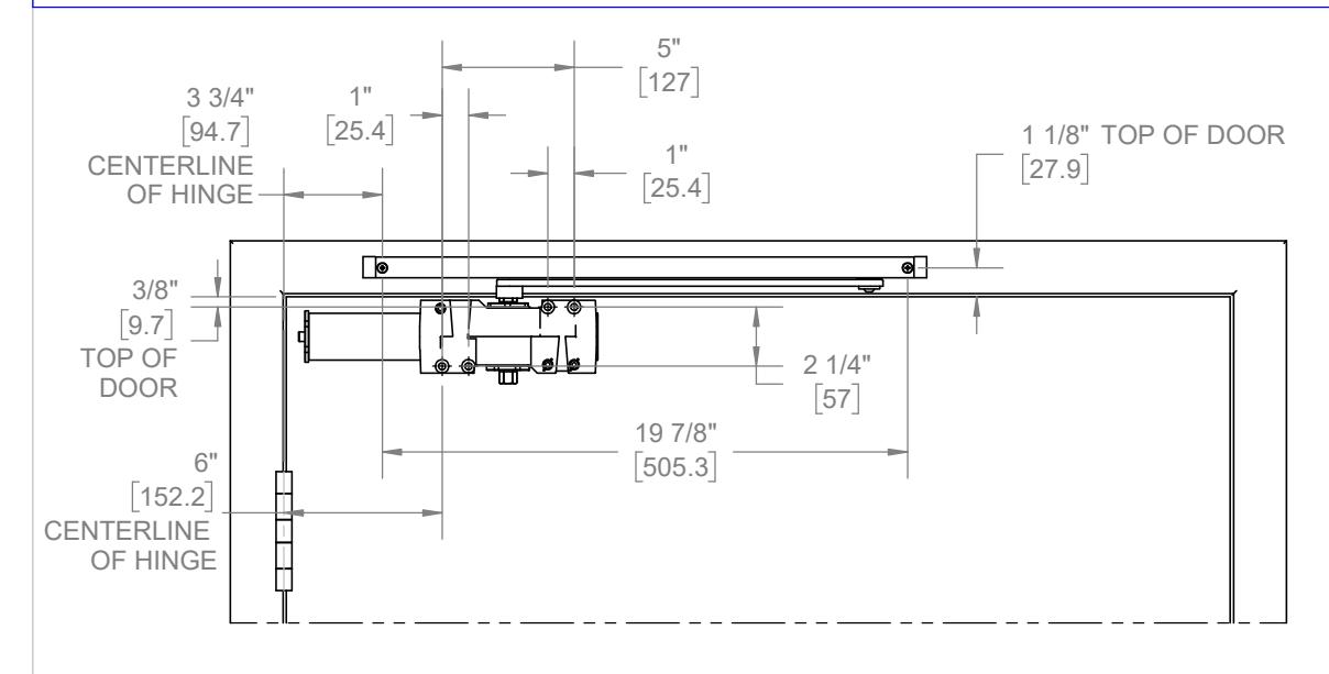
PULL SIDE APPLICATION (RIGHT HAND SHOWN) 120 TEMPLATE DOOR PREP
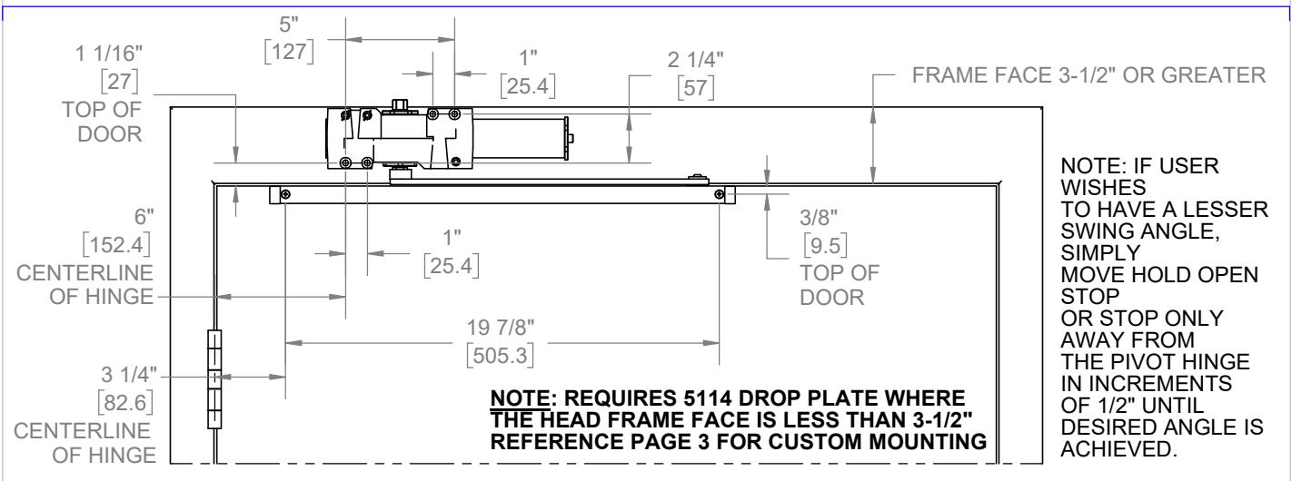
INCREMENTS OF 1/2" UNTIL DESIRED ANGLE IS ACHIEVED. NOTE: IF USER WISHES TO HAVE A LESSER SWING ANGLE, SIMPLY MOVE HOLD OPEN STOP OR STOP ONLY AWAY FROM THE PIVOT HINGE IN
Installation Sequence:
- 1. Use door prep above to locate holes on door and frame. Drill 1/8" pilot holes for the self tapping screws.
- 2. Fasten closer body to door with power adjustment port towards hinge.
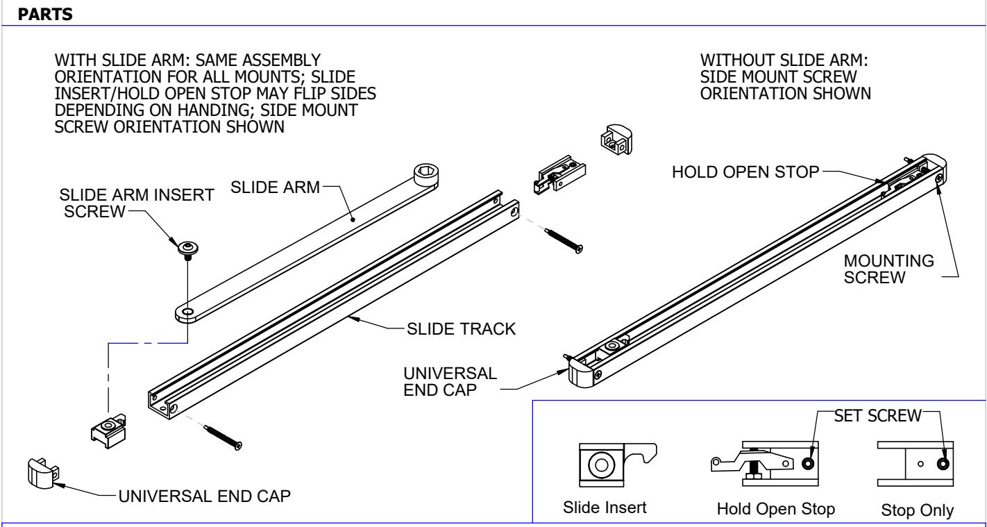
- 3. Position slide track to frame face orientated with countersink visible open side facing down and with hold open stop end toward hinge edge of door. Slide end caps on, insert screw through end caps and fasten to the frame.
- 4. Place slide arm on pinion shaft of closer so arm is positioned at a 45 degree angle out from door face.
- 5. Secure arm with arm washer and arm screw.
- 6. To properly preload closer, push arm towards door and secure other end of slide arm to track by screwing it to the slide insert. Open door to required opening angle. Then slide stop only/hold open stop up against slide insert and tighten down the stop only/hold open stop via set screw.
- 7. Determine door width, adjust spring power of closer by referencing closer adjustments on page 4.

TOP JAMB (PULL SIDE) MOUNTING APPLICATION (RIGHT HAND SHOWN) 120 ° DOOR PREP
Installation Sequence:
- 1. Use door prep above to locate holes on door and frame. Drill 1/8" pilot holes for the self tapping screws.
- 2. Fasten closer body to door with power adjustment port away from hinge.
- 3. Position slide track to frame face orientated with countersink visible open side facing down and with hold open stop end toward hinge edge of door. Slide end caps on, insert screw through end caps and fasten to the frame.
- 4. Place slide arm on pinion shaft of closer so arm is positioned at a 45 degree angle out from door face.
- Secure arm with arm washer and arm screw.
- 6. To properly preload closer, push arm towards door and secure other end of slide arm to track by screwing it to the slide insert. Open door to required opening angle. Then slide stop only/hold open stop up against slide insert and tighten down the stop only/hold open stop via set screw.
- 7. Determine door width, adjust spring power of closer by referencing closer adjustments on page 4.

Installation Sequence:
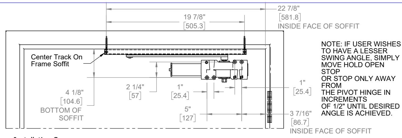
- 1. Use template to locate holes on door and frame. Drill 1/8" pilot holes for the self tapping screws.
- 2. Fasten closer body to door with power adjustment port away from hinge.
- 3. Position slide track to frame soffit with open side facing down and with hold open stop end toward hinge edge of door. Slide end caps on. Install screw up through end caps and fasten to the frame.
- 4. Connect slide arm to track by screwing it to the slide insert. DOOR MUST REMAIN IN CLOSED POSITION FOR FOLLOWING ASSEMBLY STEPS.
- 5. Swing arm toward closer and rest the hub of the arm on top of the closer pinion. Place a wrench on the bottom pinion of the closer and rotate away from the hinge (approx. 30 degrees). When the cutout of the arm hub and the pinion line up, slide the arm hub down over the pinion and secure tightly with the washer and screw. This pretensions the closer arm.
- 6. Open door to required opening angle. Then slide stop only/hold open stop up against slider insert and tighten down the stop only/hold open stop via set screw.
- 7. Determine door width, adjust spring power of closer by referencing closer adjustments on page 4.

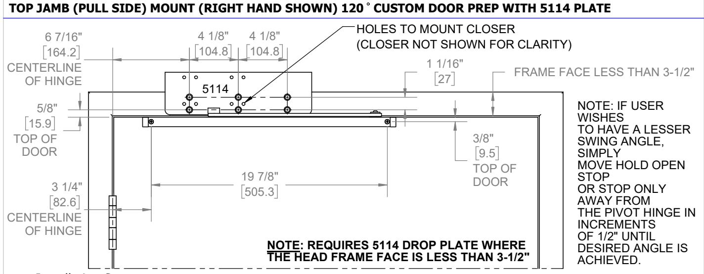
Installation Sequence:
Use door prep above to locate holes on door and frame. Drill 1/8" pilot holes for the self tapping screws. 1.
2. Fasten closer body to 5114 plate with power adjustment port away from hinge.
- Position slide track to frame face orientated with countersink visible open side facing down and with hold open stop end toward hinge edge of door. Slide end caps on, insert screw through end caps and fasten to the frame.
- 4. Place slide arm on pinion shaft of closer so arm is positioned at a 45 degree angle out from door face.
5. Secure arm with arm washer and arm screw.
- To properly preload closer, push arm towards door and secure other end of slide arm to track by screwing it to the slide insert. Open door to required opening angle. Then slide stop only/hold open stop up against slide insert and tighten down the stop only/hold open stop via set screw.
- 7. Determine door width, adjust spring power of closer by referencing closer adjustments on page 4.
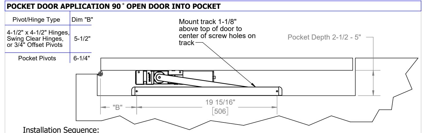
- Use template above to locate mounting holes on pocket wall and mount closer according to pull side application template on page 1. Drill 1/8" pilot holes for the self tapping screws. Determine door width, adjust spring power of closer by referencing closer adjustments on page 4.
3. Fasten closer body to door with power adjustment port away from hinge.
- 4. Fasten slide track to pocket wall face with open side facing down and with hold open stop end away from hinge edge of door. Slide end caps on, orientated with countersink visible. Screw will go through end caps as it fastens to the frame.
- Connect slide arm to track by screwing it to the slide insert. DOOR MUST REMAIN IN CLOSED POSITION FOR FOLLOWING ASSEMBLY STEPS. 5.
- 6. Swing arm toward closer and rest the hub of the arm on top of the closer pinion. Place a wrench on the bottom pinion of the closer and rotate away from the hinge (approx. 30 degrees). When the cutout of the arm hub and the pinion line up, slide the arm hub down over the pinion and secure tightly with the washer and screw. This pretensions the closer arm.
- 7. Loosen the stop only/hold open stop and open door to required opening angle. Close the door. Now slide the stop only/hold open stop back towards the hinge about 1/2" and tighten down the stop only/hold open stop via set screw.

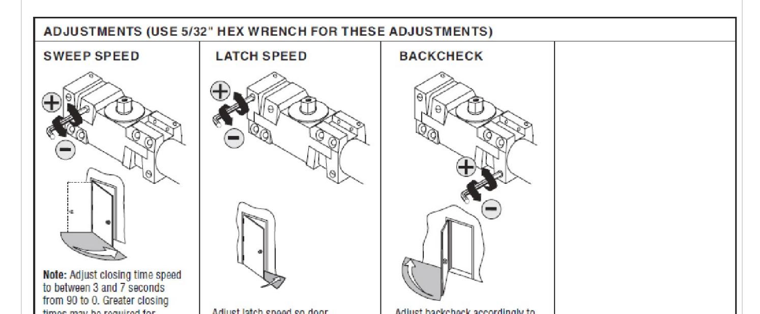
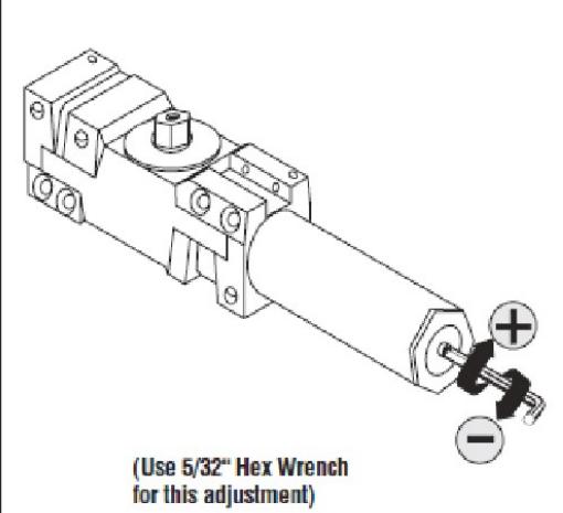
5100 DOOR CLOSER ADJUSTMENTS
| Millimuli Duul Whutii (24 ) | ||||||||||
|---|---|---|---|---|---|---|---|---|---|---|
|
24" - 30" - 36" - 42" - 48"
(610mm) (762mm) (914mm) (1067mm) (1219mm |
||||||||||
|
Regular Arm &
Top Jamb |
Size 3
(0) |
Size 4
(4cw) |
Size 5
(8cw) |
Size 6
(12cw) |
||||||
| Parallel Arm |
Size 3
(4cw) |
Size 4
(8cw) |
Size 5
(12cw) |
|||||||
| ICTIOI D | OUI WILL | uii | ||||||
|---|---|---|---|---|---|---|---|---|
| Minimum Door Width (24") | ||||||||
|
0" - 34
mm) (865 I |
4" - 60
2mm) (1524 |
~ | ||||||
|
m &
amb |
Size 1
(8ccw) |
Size 2
(4ccw) |
Size 3
(0) |
Size 4
(4cw) |
Size 5
(8cw) |
Size 6
(12cw) |
||
| Sizo 1 | Sizo 2 | Cizo 2 | Sizo A | Size 5 | ||||