44CI_install
Open the original PDF document
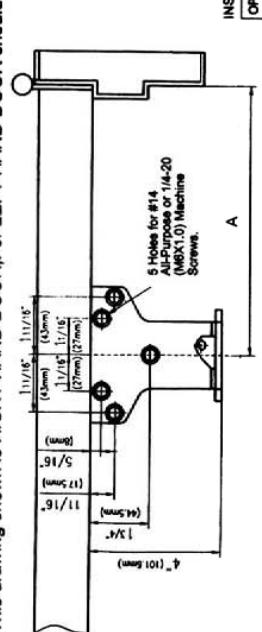
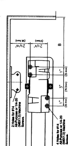
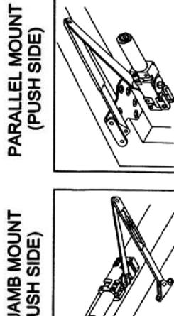
View PDFCLOSER MOUNTED ON DOOR ON PUSH SIDE PARALLEL ARM INSTALLATION
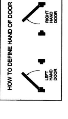
This drawing shown is RIGHT HAND DOOR, For LEFT HAND DOOR should be install in symmetry
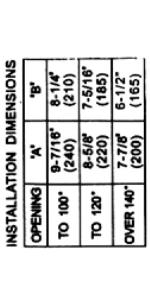
| NOTALLATION DIMENSIONS | ENGICIES | ||
|---|---|---|---|
| OPENING | .8. | ||
| TO 100° | 9-7/16* | 8-1/4" (210) | |
| TO 120° |
8-5/8'
(220) |
7-5/16"
(185) |
|
| OVER 140 | 7-7/8 | 6-1/2" |
54" (1372) 10 TURNS C.W. 60" (1524) 15 TURNS C.W.
48" (1219) 42" (1067) 36" (914) 30" (762) 8.5 lb-f*
48" (1219) 5 TURNS C.W.
0 TURNS
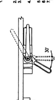
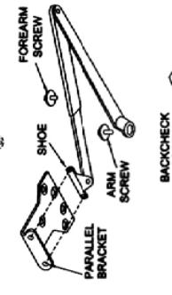
1.Before installation, turn Back Check selector valve (found on the opposite side of clears from back check acraw side) ALL THE WAY IN (CLOCKWISE). 2.Adjust spring power to match door width as indicated by chart on page 1. 3.Mount cleared on door as formanions shown. Tube and twent sides. If privit services of the clear of parallel bracket from CENTERLINE OF PRIVOT. 4.Place open and ventor hot bottom shaft and turn browned hings jamb about 30° and dithin place make am on top shaft, ineart arm acraw into top of shaft and lighten. 5.Attach four and show to preside bracket so thours. 6.Attach four and show to preside bracket as a brown. 7.Insent rold in forearm, and then heart main am to closer parallel to door. Then insent from the INLD OPEN AMI IS USED. THE NUT IS ON THE TOP FOR RH DOOR AND (IF HOLD OPEN AMI IS USED. THE NUT IS ON THE TOP FOR RH DOOR AND
REGULATION
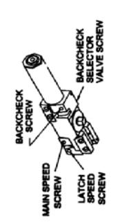
BACK CHECK To increase back-chack force, Ium ingulating acrew nearest hinge olockwise. Do nort user ABRUPT BACKCHECK OR EVECT DOOR CLOSEN TO ACT AS A DOOR STOP.
Place insert in proper cutout, then push cover against cover screw securely.
HOLD OPEN ADJUSTNENT(when hold open arm is used) Loose adjusting and, open door to desired hold open position and tighten nut. Do not permit door to swing beyond hold open setting.
Page 4
door closers International®
DOOR CLOSER MODEL: 44CI
INSTALLATION INSTRUCTION
STANDARD MOUNT (PULL SIDE)
TOP JAMB MOUNT (PUSH SIDE)

5 TURNS C.C.W. 2 TURNS C.C.W.
5 15-1
34" (864) 38" (962)
FULL TURNS REQUIRED
EXTERIOR INTERIOR DOORS DOORS
MAXIMUM DOOR WIDTH

Page 1
Spring Power Adjustment
CLOSER MOUNTED ON DOOR ON PULL SIDE STANDARD INSTALLATION
This drawing shown is LEFT HAND DOOR, For RIGHT HAND DOOR should be install in symmetry.
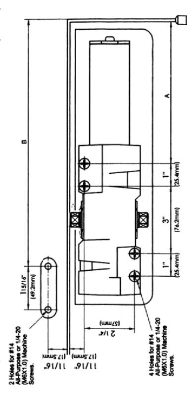
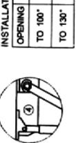
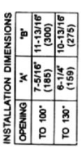
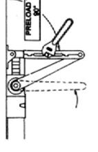
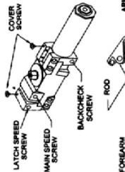
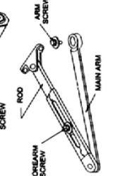
1.4 Adjust spring power to match door width as indicated by chart on page1. 2.Mount closes on doors at dimensions shown. Tube and brand intige1 pivots are used Locate closer and shoe from CENTERLINE OF PIVOT. (For offee, pivots, pis increase bre marked dimensions by 1/8?) 3. Pleco main arm on top of shaft, 1001 octoser body, insert arm screw into top of shaft and tighten. 4. Attach show to finame as subrom (if more intching power is required croate show 180") 5. Open door and insert rod in foream. 5. With foream ar right angle to door (80"), insert foream set screw and tighten. (If HOLD OPEN ARM IS USED, THE NUT IS ON THE TOP FOR RH DOOR AND BOTTOM FOR LH DOOR)
01
BACK CHECK To increase back-check force, lum regulating acrew nearest hinge clockwise. Do NOT USE ABRUPT BACKCHECK OR EXPECT DOOR CLOSER TO ACT AS A DOOR STOP.
HOLD OPEN ADJUSTMENT(when hold open arm is used) Loose adjusting nut, open door to destred hold open position and tighten nut. Do not permit door to swing beyond hold open setting. COVER Place insert in proper cutout, then push gover against door . Tighten both cover screw securely.
CLOSER MOUNTED TOP JAMB ON PUSH SIDE OF DOOR TOP JAMB INSTALLATION
For LEFT HAND DOOR should be install in symmetry. This drawing shown is RIGHT HAND DOOR,
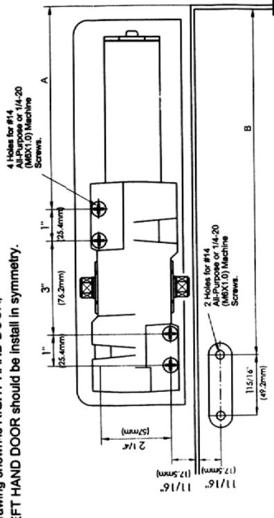
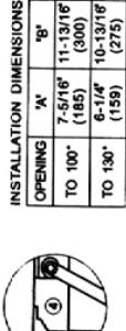
1 Adjust spring power to match door width as inclicated by chart or page 1. 2 Mount closer on frame as dimension shown. Tube and toward hinge. If prots are used choses doors and abon from CEMPEQLE (D. PVIOT. \nused choses doors and show from CEMPEQLE (D. PVIOT. 10 Con flast plocks, pis increase the marked dimensions by 167) 3 Place main arm on top of shaft 100°10 closer body, insert arm screw into top of shaft and lighten. 4 Atlant shoe to door as shown.(If more latching power is required, rotate shoe 180°) 5 Open door and insert not in forearm-for reveal 2 50° through 4 13° ble 4 close for reveal 4 70° is 0° tues FOREARM ENTORE/R(ROD)-available from dealer. 8 With forearm at right angle to door (90°), insert forearm set screw and lighten. 8 With Coperum ARM IS USED. THE NUT IS ON THE BOTTOM FOR RH DOOR AND TOP FOR LH DOOR.
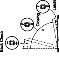
REGULATION: AREGULATION: ARequirement and polyagen position to door alop position is 4-6 secs, eventy divided between main swing speed and latch swing speed. Use sociate eventy divided between main swing speed and latch swing speed. Las sociate specification to subject speed, in o solve steeper, for solve steepers, than regulating screen inserest statist doctowise. To slow airch speed, furn regulating screen resents that necessarial statistics. 3ACK CHECK
LATCH SPEED SCREW
SCREW
To increase back check force, turn regulating screw nearest hinge clockwise. DO NOT USE ABRUPT BACKCHECK OR EXPECT DOOR CLOSER TO ACT AS A DOOR STOP.
Place insert in proper cutout, then push cover against frame. Tighten both cover screw securely.
HOLD OPEN ADJUSTMENT(when hold open arm is used) Loose adjusting flut, open door to desired hold open position and tighten nut. Do not permit door to swing beyond hold open setting.
Page 2
Page 3