295-Installation Instructions
Open the original PDF document
View PDF

801 Avenida Acaso, Camarillo, Ca. 93012 • (805) 494-0622 • Fax: (805) 494-8861 www.sdcsecurity.com • E-mail: service@sdcsecurity.com
INSTALLATION INSTRUCTIONS Model 295 – Programmable Cabinet Lock
Features & Applications
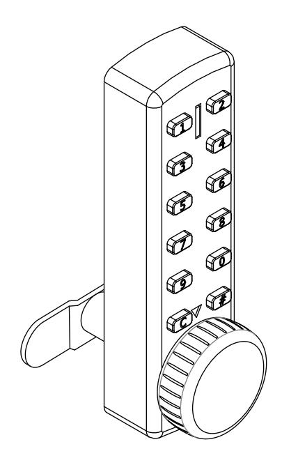
- Ideal for new installations, or a quick retrofit for keyed cam locks
- Suitable applications include: cabinets, cupboards, medical carts, lockers, etc.
- Keypad with 12 individual buttons (0-9, C, #)
-
Easily programmable codes:
- 1 Master Code, 1 Sub-master Code, & 30 User Codes
- Configurable code length 4 to 6 digits
- Three Operation Modes available:
Multiple User mode, Code Free mode, & Single Use mode (locker mode)
- 15,000 operations on 2 x AAA batteries (included)
- Non-volatile memory
- Battery failure override using a 9V battery and Master Code
Installation
Parts Included:
- Cabinet Lock w/ key cylinder and spindle
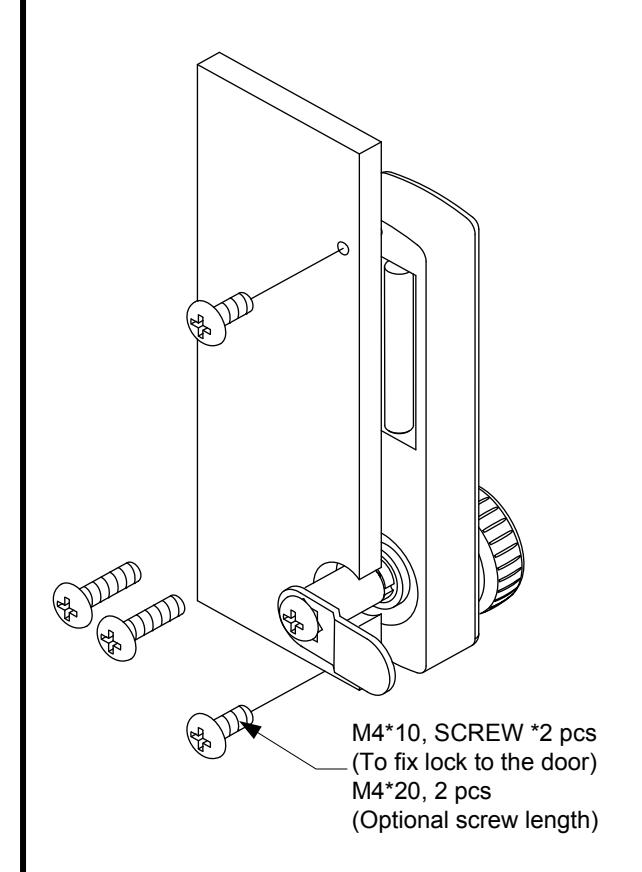
- Lock mounting screw & lock washer (x 2)
- Cam, cam mounting screw & lock washer
- Keys (x2)
- Installation instructions & template
Technical Information:
- Door Thickness: up to 3/4"
- Cam mounting: 5/16" square spindle
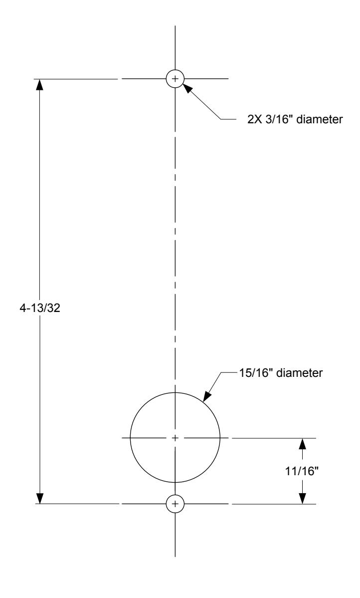
- Hole required for spindle: 15/16" diameter
- Batteries: 2 x AAA Alkaline (included)
Replacing an existing cam lock with the Cabinet Lock:
- 1. Remove existing cam lock.
- 2. Place supplied template over the existing hole. Align the 15/16" spindle hole on the template with the hole left by cam lock. Mark the upper & lower mounting holes.
- 3. Drill the two 3/16" mounting holes.
- 4. Mount the cabinet lock to the door using the supplied lock washer & mounting screws.
- 5. From the inside of the door select and attach the appropriate cam using the supplied cam mounting screw & washer.
- 6. Before closing and locking the door, test the operation of the lock using the default Master and User Codes (See Basic Operation on page 2).
- 7. It is recommended that the default Master and User Codes be changed at this time (See Quick Start Programming on page 2).
New installations:
1. Place the supplied template on door.
NOTE : Before drilling fixing holes, verify that the position of the Cabinet Lock when fitted will allow enough clearance for the cam to work.
2. Continue the installation from steps 3 though 7 above.
Programming Overview
Operational Notes
- The 295 can store 1 Master Code, 1 Sub-Master Code, and up to 30 User Codes (ID Number 01 through 30).
- Codes may be 4, 5, or 6 digits long. The length of the Sub-Master Code and User Codes <u>must</u> be the same length as the Master Code.
- Changing the length of the Master Code from the default length (5 digits) will delete the existing Sub-Master Code and all other User Codes.
- The "C" button may be used to clear a previous entry code if a mistake is made.
- If an incorrect code is entered 3 times, the 295 keypad will be locked out for a period of 10 seconds.
Operational Modes
NOTE: Before changing the default programming codes, decide which operation mode best suits your application.
There are two (2) user modes:
<u>Multiple User Mode</u>: This is the default mode. Up to 30 different user codes may be programmed. Each user code can be used multiple times.
<u>Single Use Mode (Locker Mode)</u>: The lock is normally unlocked. The user enters a single use code which will lock the cabinet lock. Reentering the same user code will open the lock only once and then be erased. The lock will now remain unlocked until the next single use code is entered into the lock.
If Single Use Mode is desired,
- Step 1 Proceed to Advanced Programming. Enter Programming Mode.
- Step 2 Use Function 01 to set the user code length and change the default Master Code.
- Step 3 Use Function 12 to change the lock mode to Single Use Mode.
- Step 4 Use Function 00 to Exit Programming Mode.
Factory Reset Procedure (if Master Code is lost)
- Remove one of the batteries
- Press & hold the "C" button and replace the battery
- Wait until the Blue LED flashes twice, and release the "C" button
- Within 3 seconds, Press the "C" button three times
{The Blue LED will flash twice and the lock will be reset to factory default}
Battery Fail Override (in lieu of key override)
- Place the contact points of a 9V battery against the contact points at the bottom of the cabinet lock (The positive +9V terminal should line up with the "#" button and the negative -9V terminal with the "C" button.)
- Enter the Master Code. When the motor activates, remove the battery and open the lock. Replace the expired batteries.
Function Summary
| Function | Minimum Access Level | ||
|---|---|---|---|
| No. | Function Description | Master | Sub-Master |
| Enter Programming Mode | Х | х | |
| 04 | Add/Change User Code | Х | х |
| 05 | Delete ALL User Codes | х | х |
| 06 | Suspend Any User Code | х | х |
| 07 | Restore Any User Code | х | х |
| 08 | Suspend ALL User Codes | х | х |
| 09 | Restore ALL User Codes | х | х |
| 13 | Hold Open (Code Free Mode) | х | х |
| 14 | Cancel Hold Open | х | х |
| 15 | Change Unlock Time | х | х |
| 01 | Change Master Code/Code Length | х | |
| 02 | Add/Change Sub-Master Code | х | |
| 03 | Delete Sub-Master Code | х | |
| 11 | Change to Multilple User Mode | Х | |
| 12 | Change to Single Use Mode | Х | |
| 80 | Reset to Factory Settings | Х | |
| 00 | Exit Programming Mode | Х | х |
NOTE: Although Users do not have programming rights, any user may change their individual code by performing the following steps:
Example,
Old Code: 56789, New Code: 98765
Advanced Programming
Before any function is performed, you must first Enter Programming Mode.
NOTE : It is important that you wait for the appropriate LED response before continuing to the next intermediate step.
After entering programming mode, you have 30 seconds to press any key before the unit automatically exits programming mode.
Once a function # is entered, you have 5 seconds between intermediate steps. If you take too long and get a Red LED, wait until you see the blue pulse every 2 seconds, and restart the function.
After completing any function, the BLUE LED will blink twice (1 flash per second) as confirmation. The unit will remain in programming mode until you exit programming mode using Function 00, or by waiting 30 seconds for the automatic timeout.
| Enter Programming Mode | ||
| LED | ||
| Press # 12345 (B) (The Blue LED will pulse once every two seconds | while in programming mode.} | |
| Function 00: Exit Programming Mode | ||
| LED LED | ||
| Press 00 B # BB | ||
| Function 01: Change the Master Code / Change Code Length | ||
| LED LED LED | LED LEI | |
| Press 01 B Length of Code B Enter new Master code B Re-enter Ler LED LED LED LED LED | ngth of Code (B) Re-enter Master Code (B)(E | |
| ength = 5. Sets the Master Code to '99999'} | ||
| Function 04: Add or Change a User Code | DRTANT: | |
|
|
ID# ranges from 01 to 30. Codes must be same length as Master Code. | |
| Codes must be same length as Master Code. Codes must be unique or they will be rejected. | ||
| LED LED LED | 7051 | |
| Example: 04 B 02 B 98765 B Adds User ID 02 with code '987 | 765'} | |
| Function 05: Delete All User Codes | IMPORTANT: All codes (User ID 01 – 30) will be erased. | |
| LED Press 05 (B) 05 {LED will pulse quickly, and then flash for 1 second} | Master & Sub-Master Codes are not affected. | |
| Pless 05 (B) 05 (LLD will pulse quickly, and then liast for 1 second) | ||
| Function 06: Suspend Any Authorized User Code | IMPORTANT: | |
| LED LED | User ID# ranges from 01 to 30. | |
| Press 06 B User ID# BB | If User ID # is not an authorized user, an error will occur. | |
| LED LED Example: 06 B 10 BB {User code with User ID 10 is suspended} | ||
| Function 07: Restore Any Authorized User Code LED LED | IMPORTANT: User ID# ranges from 01 to 30. | |
| LED LED Press 07 ® User ID# ®® | If User ID # is not an authorized user, an error will | |
| LED LED | occur. | |
| Example: 07 B 10 B (User code with User ID 10 is restored acces | s} | |
| Function 08: Suspend ALL Authorized User Codes | IMPORTANT: | |
| LED LED | Any users added after this function is activated, will also be suspended. | |
| Press 08 B 08 B (All authorized user codes are suspended) | Master & Sub-Master Codes are not affected. | |
| Function 09: Restore ALL Authorized User Codes | ||
| LED LED A ROBERT AND AND AND AND AND AND AND AND AND AND | ||
| Press 09 B (All authorized users are restored access) | ||
Function 13: Hold Open (Code Free Mode) LED LED {The unit is continuously unlocked} Press 13 B 13 B B Function 14: Cancel Hold Open LED LED Press 14 B 14 BB {The unit relocks and returns to normal operation} Function 15: Change Unlock Time IMPORTANT: Default = 3 seconds LED Open Time BB Open Time may be set from 1 to 9 seconds. Press 15 B LED LED Example: 15 B 5 BB {Unlock time is set to 5 seconds} Function 02: Add/Change Sub-Master Code IMPORTANT: LED Sub-Master Code must be same length as Master Code. Press 02 B New Sub-Master Code BB LED LED Example: 02 B 22222 BB {Sets the Sub-Master code to '22222'} Function 03: Delete Sub-Master Code LFD LED Press 03 B 03 BB {Deletes Sub-Master Code} Function 11: Change from Single Use Mode to Multiple User Mode IMPORTANT: LED Performing Function 11 will reset all programming LED back to the factory default settings. Press 11 B 11 BB Function 12: Change from Multiple User Mode to Single Use Mode LED (The unit will remain unlocked. Entering a single use code will lock the unit. Re-entering the same code will Press 12 B 12 B B open the lock only once and then be erased. The unit will again remain unlocked until the next single use code is entered into the lock}. Function 80: Reset to Factory Default Settings LED Press 80 B 80 B B {The lock programming is set to the factory default settings} Default Settings The 295 Cabinet Lock comes pre-programmed with the following default settings. Pressing any of the default codes will unlock the unit: Master Code = 12345 {Required for programming mode. This code may be changed, but not deleted}. User Code #01 = 54321 This is User 01. the 295 can store up to 30 User Codes (numbers 01 through 30).
This code may be changed or deleted.
{This code can perform most programming functions. See Advanced programming}. Sub Master Code = None
{This code length may be set to 4, 5 or 6 digits}. Code Length = 5 digits
Unlock Time = 3 seconds {The amount of time, in seconds, a user has to turn the latch once a valid code is entered).
Incorrect Code Lockout Time = 10 seconds {Locks out the keypad after (3) incorrect attempts. This is a fixed amount of time}.
LED Status Legend
Blue LED – Single pulse (0.1 sec duration) = Keypad button pressed.
Blue LED - Single Flash (1 sec duration) = User code accepted, OR Programming function/step accepted.
Blue LED – Double Flash (1 flash per sec) + Entering/Exiting programming mode, OR Programming function completed.
Blue LED – Repeating pulse (1 pulse every two sec) = In programming mode.
Red LED – Single Flash (1 sec duration) = Code rejected, OR Programming error.
Blue & Red LED – Single pulse (0.1 sec duration) – System power on, OR User code suspended.
Installation
Model 295 – Programmable Cabinet Lock Mounting Template
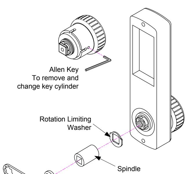
Cams (2) Straight, Offset Spindle Cap
Installation Lock Washer
M6*25 screw M6*5 screw (optional) (To fix cam and other parts to the lock)