2400 Flush Mount Electromagnetic Holder – Installation Template
Open the original PDF document
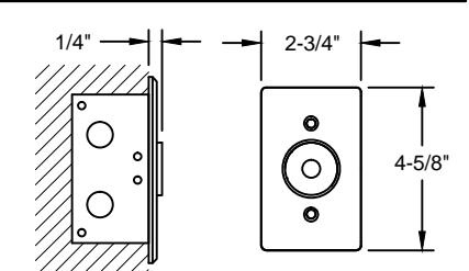
View PDF2400 ELECTROMAGNETIC DOOR HOLDER, FLUSH WALL MOUNT
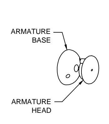

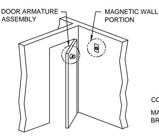
FRONT VIEW
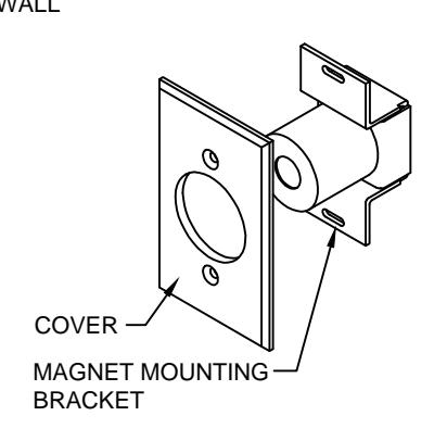
2400 MAGNETIC WALL PORTION
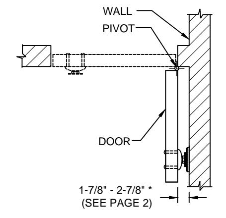
ELECTRICAL DATA:
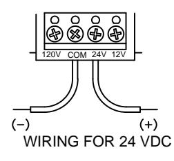
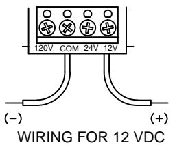
THIS PRODUCT IS AN ELECTROMAGNETIC HOLDING DEVICE, INTENDED FOR USE IN FIRE DOOR APPLICATIONS, BUT CAN BE USED FOR OTHER MAGNETIC APPLICATIONS. WIRE INTO PROPER TERMINALS AS NOTED BELOW:
| SERIES | VOLTAGE | DC/mA | DC/VA | AC/mA | AC/VA | TERMINALS |
|---|---|---|---|---|---|---|
| 2400 | 12 DC | 60 | .72 | Com & 12 v | ||
| 24 AC/DC | 30 | .72 | 30 | .72 | Com & 24 v | |
| 120 AC | 30 | 3.60 | Com & 120 v |
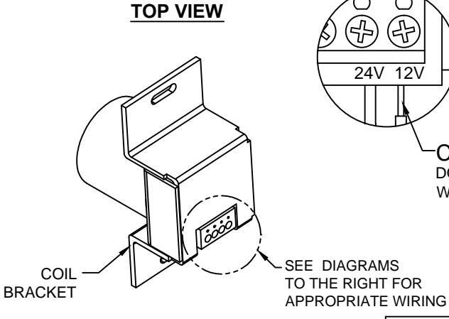
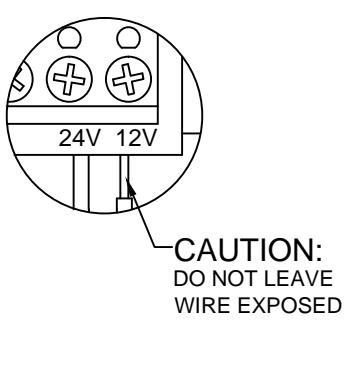
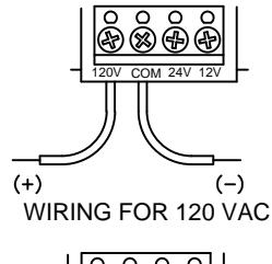
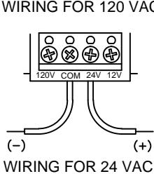
| SCREW DETAIL | |||||||||
|---|---|---|---|---|---|---|---|---|---|
| QTY | SCREW | ||||||||
| MAGNETIC WALL PORTION | 2 | 6-32 x 1" OVAL HEAD MACHINE SCREW | |||||||
| MAGNETIC COVER | 2 | 6-32 x 1" FLAT HEAD MACHINE SCREW | |||||||
| DOOD ADMATURE | 2 | 10-32 x 1" PAN HEAD MACHINE SCREW | |||||||
| DOOR ARMATURE | | 2 | 10-32 x 1-1/4" SNB | |||||||
® www.abhmfg.com
E-mail: abhinfo@abhmfg.com Architectural Builders Hardware Mfg., Inc. 1222 Ardmore Ave., Itasca, IL 60143 630.875.9900; FAX 800.9FAXABH (932.9224)
ABH is a minority owned and operated manufacturing company.
© 2015 ABH Mfg., Inc. printed in USA
PAGE 1 OF 2 REVISED 07-09-15
2400-1-04.DWG
2400 ELECTROMAGNETIC DOOR HOLDER, FLUSH WALL MOUNT
WALL PORTION INSTALLATION:
- 1. Measure distance from pivot centerline to wall (Dim. "A").
- 2. Determine door width (Dim. "B").
-
3. Use table below to locate magnet box on wall (Dim. "C").
- a. Example: Dim. "A" = 10" Dim. "B" = 42" Result Dim. "C" = 38-1/2".
- b. If Dim. "A" or Dim. "B" Falls between dimensions listed in the table below, allow for difference.
Example: Dim. "A"= 7" Dim. "B" = 36" Estimated Dim. "C" = 32-15/16"
c. If Dim. "A" and Dim. "B" intersect in the shaded area, DO NOT INSTALL magnet box. The degree of door opening will not allow for proper alignment between armature and wall magnet.

- 5. Check degree of door opening shown in table and coordinate with door closer and other door hardware.
- 6. Total projection of door hardware must not be more than 2-7/8" on the pull side of door. If greater, you will need to use additional extensions, sold separately.
| DIM. "B" (DOOR WIDTH) | ||||||||||||||||||||||
|---|---|---|---|---|---|---|---|---|---|---|---|---|---|---|---|---|---|---|---|---|---|---|
| Dim. | 28 | 30 | 32 | 34 | 36 | 38 | 40 | 42 | 44 | 46 | 48 | |||||||||||
| Dim "C" | Deg | Dim "C" | Deg | Dim "C" | Deg | Dim "C" | Deg | Dim "C" | Deg | Dim "C" | Deg | Dim "C" | Deg | Dim "C" | Deg | Dim "C" | Deg | Dim "C" | Deg | Dim "C" | Deg | |
| 2 | 25-3/8 | 90° | 27-3/8 | 90° | 29-3/8 | 90° | 31-3/8 | 90° | 33-3/8 | 90° | 35-3/8 | 90° | 37-1/4 | 90° | 39-3/8 | 90° | 41-3/8 | 90° | 43-3/8 | 90° | 45-3/8 | 90° |
| 4 | 25-1/4 | 95° | 27-1/4 | 94° | 29-1/4 | 94° | 31-1/4 | 94° | 33-1/4 | 94° | 35-1/4 | 93° | 37-3/8 | 93° | 39-3/8 | 93° | 41-3/8 | 93° | 43-3/8 | 93° | 45-3/8 | 93° |
| 6 | 25 | 99° | 27 | 99° | 29-1/8 | 98° | 31-1/8 | 98° | 33-1/8 | 97° | 35-1/8 | 97° | 37-1/8 | 96° | 39-1/8 | 96° | 41-1/8 | 96° | 43-1/8 | 95° | 45-1/8 | 95° |
| 8 | 24-5/8 | 104° | 26-5/8 | 103° | 28-3/4 | 102° | 30-3/4 | 101° | 32-3/4 | 101° | 34-7/8 | 100° | 36-7/8 | 99° | 38-7/8 | 99° | 40-7/8 | 99° | 43 | 98° | 45 | 98° |
| 10 | 24 | 109° | 26-1/8 | 107° | 28-1/4 | 106° | 30-1/4 | 105° | 32-3/8 | 104° | 34-3/8 | 103° | 36-1/2 | 103° | 38-1/2 | 102° | 40-5/8 | 101° | 42-5/8 | 101° | 44-5/8 | 100° |
| 12 | 23-1/4 | 114° | 25-3/8 | 112° | 27-5/8 | 110° | 29-3/4 | 109° | 31-3/4 | 108° | 33-7/8 | 107° | 36 | 106° | 38 | 105° | 40-1/8 | 104° | 42-1/8 | 103° | 44-1/4 | 103° |
| 14 | 22-1/4 | 119° | 24-1/2 | 116° | 26-3/4 | 114° | 28-7/8 | 113° | 31-1/8 | 111° | 33-1/4 | 110° | 35-3/8 | 109° | 37-1/2 | 108° | 39-1/2 | 107° | 41-5/8 | 106° | 43-3/4 | 105° |
| 16 | 23-1/2 | 121° | 25-3/4 | 119° | 28 | 117° | 30-1/4 | 115° | 32-3/8 | 114° | 34-5/8 | 112° | 36-3/4 | 111° | 38-7/8 | 110° | 41 | 109° | 43-1/8 | 108° | ||
| 18 | 24-1/2 | 123° | 26-7/8 | 121° | 29-1/4 | 119° | 31-1/2 | 117° | 33-3/4 | 116° | 35-7/8 | 114° | 38-1/8 | 113° | 40-1/4 | 112° | 42-3/8 | 111° | ||||
| 20 | 28 | 123° | 30-3/8 | 121° | 32-5/8 | 119° | 35 | 117° | 37-1/4 | 116° | 39-3/8 | 115° | 41-5/8 | 114° | ||||||||
| 22 | 31-1/2 | 123° | 33-7/8 | 121° | 36-1/8 | 119° | 38-3/8 | 118° | 40-5/8 | 116° | ||||||||||||
| 24 | 35 | 122° | 37-1/4 | 121° | 39-5/8 | 119° | ||||||||||||||||
- 7. From corner of wall, measure the appropriate Dim. "C" determined in step 3.
- 8. Proper electrical wire routing must be done before installing electrical box.
- 9. The electrical box should be installed with reinforcement to withstand a minimum 50 lb. pull (not provided with unit).
IMPORTANT : a. Check that power voltage equals one of the voltages labeled on back of magnet.
b. Consult " ELECTRICAL DATA" on page 1.
DOOR ARMATURE INSTALLATION:
- 1. Place and center the door armature on the surface of the magnet with the two holes of the base aligned horizontally.
- 2. Gently close the door and adjust the angle of the door armature so the base lays flat against the door.
- 3. While keeping slight pressure on the door, mark location of door armature through the two base holes.
- 4. Drill through the door where the two marks are located with 5/16" drill. Fasten armature with the (2)10-32 machine screws & sex bolts provided.
NOTE: 1. All dimensions are provided in inches, unless noted otherwise.
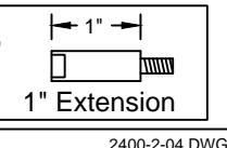
2. Additional extensions can be ordered separately to increase the door armature projection: 3/8", 1/2", 3/4", 1", 2" 4" or 6".
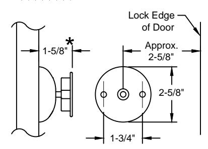
★ For 2-5/8" Door Projection, use 1" Extension provided complimentary
В
Pivot
Centerline
Magnet Box
Centerline
С
A :H
www.abhmfg.com E-mail: abhinfo@abhmfg.com Architectural Builders Hardware Mfg., Inc. 1222 Ardmore Ave., Itasca, IL 60143 630.875.9900; FAX 800.9FAXABH (932.9224)
ABH is a minority owned and operated manufacturing company.
2400
© 2015 ABH Mfg., Inc. printed in USA
PAGE 2 OF 2 REVISED 07-09-15